Air requirements, Span and zero adjustment, Cam adjustment – Flowserve PM15 Pneumatic Valve Positioner User Manual
Page 4: Worcester controls
4
PM15 Pneumatic Valve Positioner Installation, Operation and Maintenance Instructions
WCAIM2016
Flow Control Division
Worcester Controls
1
7
8
3
5
6
4
2
1
3
2
4
7
6
5
Correct
Incorrect
3
2
1
1-2 mm (
1
/
16
")
4
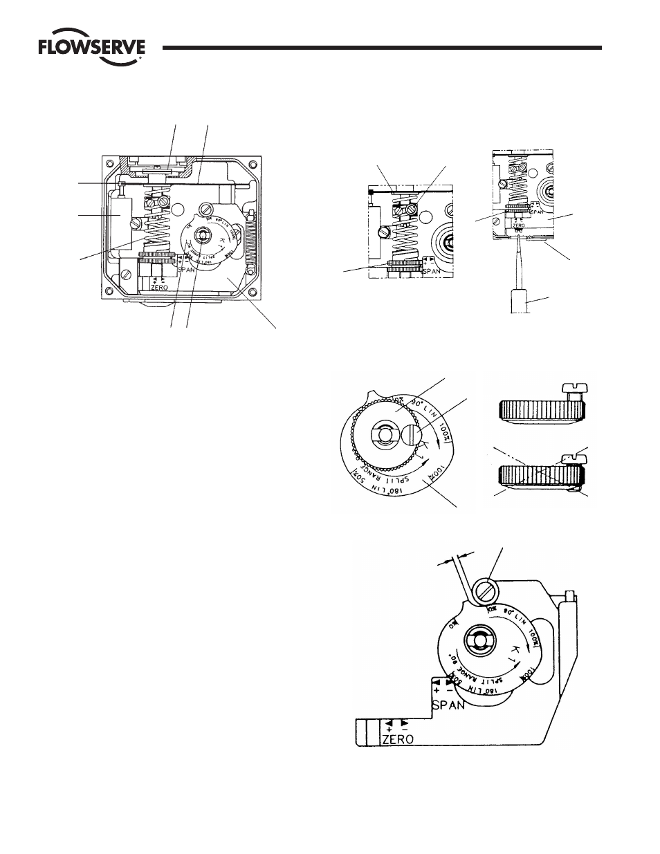
Operation
Span and Zero Adjustment
Cam Adjustment
4. AIR REQUIREMENTS
Maximum supply pressure is 0.9 MPa (125 psi).
Supply air shall be clean, dry and free from oil, water, moisture,
foreign parts and debris.
The air shall be freeze-dried or similar to a dew point of at least 10˚C
(18˚F) below lowest expected ambient temperature.
A <40 micron filter/regulator is recommended to be installed as close
to PM15 as possible to ensure proper supply air quality.
5. SPAN AND ZERO ADJUSTMENT
Span is adjusted with the brass-colored (upper) thumb wheel (1)
located on the feedback spring.
To adjust the span, always return to minimum input signal first, then
loosen the locking screw (2) and turn thumb wheel (1). Tighten screw
(2) when span is set. Do not allow the top of the spring to contact the
spring guide (3).
Always check zero after adjusting span.
Zero is adjusted by turning the silver (lower) thumb wheel (4) located
on the lower arm (5) or externally with a screwdriver (7), through the
zero adjustment opening. Remember to install cover (6) to ensure the
units sealing.
6. CAM ADJUSTMENT
With the cover and indicator removed, loosen the screw (1) and turn
the cam locking nut (2) counterclockwise until the cam loosens.
Adjust the cam (3) as desired making sure that the ball bearing (4)
always is riding on an active lobe on the cam. To secure the cam,
make sure that screw (1) is backed out from the locking nut (2) then
finger tighten the locking nut and tighten screw (1). Install and adjust
the indicator and reinstall cover.