Technical data, Spare parts list, Worcester controls – Flowserve PM15 Pneumatic Valve Positioner User Manual
Page 7
WCAIM2016
PM15 Pneumatic Valve Positioner Installation, Operation and Maintenance Instructions
7
Flow Control Division
Worcester Controls
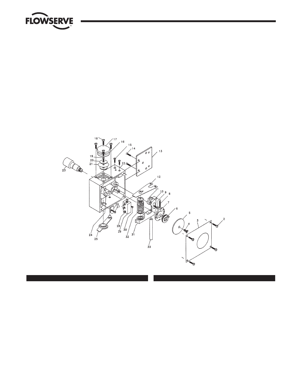
Exploded Drawing
10. TECHNICAL DATA
Input Signal
20–100 kPa/3–15 psi
Linearity
< 0.5%*
Hysteresis
< 0.5%*
Repeatability
< 0.5%*
Gain Factor at:
80% Load
(Supply Pressure 0.6 MPa/87 psi)
250 kPa/kPa psi/psi +20%
50% Load
(Supply Pressure 0.6 MPa/87 psi)
500 kPa/kPa psi/psi +20%
Air Consumption at Supply Pressure:
± 20%
0.6 MPa/87 psi
7.5 nl/min (0.27 scfm)
Air Delivery at Supply Pressure:
± 20%
0.2 MPa/29 psi
135 nl/min (4.7 scfm)
0.4 MPa/58 psi
240 nl/min (8.4 scfm)
0.6 MPa/87 psi
340 nl/min (11.9 scfm)
Supply Pressure
Max 0.9 MPa/125 psi
Temperature Range
-20˚C to +85˚C (-4˚F to 185˚F)
Connector Threads
1
/
4
" NPT
Weight
1.1 kg/2.4 lb
Housing
Die Cast Aluminum
Surface Treatment
Epoxy Painting
*Percent of full scale.
Item
Qty
Description
2, 4, 9, 15, 1 Set
P4 Screw Set
18, 19, 20,
27, 30
3
1
P4-3 Front Cover
5
1
P4-5 Indicator Arrow-Standard
6
1
P4-6 Cam Locking Nut
7
1
P4-K1 Cam
8
1
P4-8 Lower Arm Spring
12
1
P4-12 Balance Arm
13, 14
1
P4-13 Adapter Plate
16, 17
1
P4-17 Diaphragm Cover with Nitrile O-Ring
Item
Qty
Description
20, 21
1
P4-20 Diaphragm Assembly/Nitrile
23
1
P4-C3 Spindle
24
1
P4-24 Mounting Hole Sealing Cap
25
1
P4-25 Zero Adjust Cover
26
1
P4-26 Lower Arm Stop Plate
28
1
P4 O-Ring Set, Nitrile
29
1
P4-29 Pilot Valve Assembly
31, 10, 11
1
P4-31 Lower Arm Assembly
32
1
P4-32 P4 Spring Assembly, 12 psi
33
1
P4-33 Guide Rod
11. SPARE PARTS LIST