Reverse-acting and split-range, Maintenance, Worcester controls – Flowserve PM15 Pneumatic Valve Positioner User Manual
Page 5
WCAIM2016
PM15 Pneumatic Valve Positioner Installation, Operation and Maintenance Instructions
5
Flow Control Division
Worcester Controls
7. REVERSE-ACTING AND SPLIT-RANGE
Reverse-Acting
For reverse-acting operation, invert cam. Also reverse connections
C1 and C2. For single-acting actuators, move actuator connection
from C2 to C1 and plug C1.
Split-Range
For split-range, reposition the cam, noting the markings on the cam—
for 3–9 psi use initial 50% zone; from 9–15 psi, use 51–100% zone.
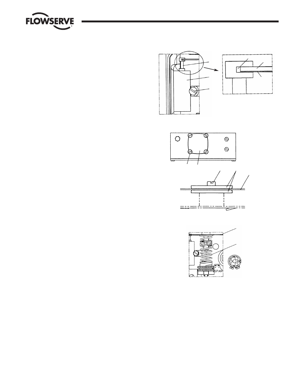
8. MAINTENANCE
A. PILOT VALVE
To remove the pilot valve for cleaning or inspection, remove the
screw (1) and carefully lift out the complete assembly (2). Gently
remove the spool (3) from the block and clean the parts, using
methylate cleaner or similar. Blow the parts dry with compressed
air.
Should the parts show signs of wear, a new assembly is
recommended. Mixing spool valves and valve bodies may result
in very high bleed rates and poor performance. Check the O-rings,
then secure and install the pilot valve assembly to the positioner
unit and secure it with the screw (1). Make sure that the leaf
spring (4) on the balance arm (5) is properly fitted in the groove
on spool (6). Check again to ensure smooth operation of the
assembly.
To maintain original factory performance specifications, use only
Worcester spool valve assemblies.
B. DIAPHRAGM
Loosen screws (1) and remove the diaphragm cover (2).
Loosen screw (3), diaphragm (4) and washers (5) can be
removed.
When installing the diaphragm, make sure to place one washer on
each side of the diaphragm. Make sure that the raised circle on
the washer is facing the diaphragm.
Install the screw (3) and tighten.
Check the O-ring on the diaphragm cover (2), then install
and secure the cover with screws (1).
C. FEEDBACK SPRING
Once the front cover and indicator are removed, the
feedback spring can be easily accessed.
Hold the spring (1) from the top, pull down and out.
When installing, hold the assembly at the top, guide the lower
part to position on the zero screw, then press down until it fits
easily under the balance arm (2). Make sure that the assembly is
aligned properly against the lower arm and the notch is engaged
in the tab on the balance arm (2).
D. BALANCE ARM
The balance arm can only be removed after diaphragm and
feedback spring have been removed. (See Section 8.C. and
Section 8.B.)
Loosen the screws (3) and the balance arm can be removed.
When installing the balance arm make sure that the leaf spring (4)
on the underside of the balance arm (5) is properly engaged into
the groove (6) of the spool in the pilot valve.
Tighten the two screws (3) holding the balance arm to the
positioner.
Maintenance — Pilot Valve
Maintenance — Diaphragm
Maintenance — Feedback Spring
3
2
1
6
5
4
2
1
3
5
4
2
1