Air supply and electrical installation, Worcester controls – Flowserve 10 ACCESS I Worcester Controls User Manual
Page 3
WCAIM2028
10, 15, 20 ACCESS I and 10-40 Access M 39 Actuators Intrinsically Safe
3
AIR SUPPLY AND
ELECTRICAL INSTALLATION
A. 1. Air
Supply:
The Series 39 Actuator is factory lubricated. For optimum
operation, the use of filtered and lubricated air is
recommended.
2. Air Supply Pressure:
Intrinsically Safe versions of double-acting actuators require
40–100 psig supply air. Spring-return actuators require
80–100 psig supply air. Spring-return actuators can also be
set up to operate on supply air pressures ranging from 40–80
psig by using fewer springs. See “Rebuilding Instructions”,
Spring-Return Actuator, for proper number and location of
springs for reduced supply air pressures.
3. Air Supply Connection:
Connect air supply to
1
/
4
" NPT connection on control block. For
units with no integral solenoid valve, air connection block has
two
1
/
4
" NPT connections for inlet air (only one used for
spring-return units).
4. Recommended Tubing Sizes:
In order to provide sufficient flow of supply air to the Series
39 actuator, the following tubing sizes are recommended:
Actuator Size
Runs Up To 4 ft. Long
Runs Over 4 ft. Long
10, 15, 20, 25
1
/
8
"
1
/
4
"
30 and larger
1
/
4
"
3
/
8
"
5. Air
Consumption:
The following chart shows the amount of pressurized (80
psig) air consumed per stroke in cubic feet. To determine the
total amount of air consumed per complete cycle for double-
acting actuators, simply add the volumes for both the opening
and closing strokes together; for spring-return units, the total
volume of air consumed is the volume shown for the opening
stroke.
Actuator Size
Stroke
1039
1539
2039
2539
3039
3339
3539
4039
Open
.04
.08
.16
.28
.43
.65
.90
1.26
Close
.05
.09
.17
.30
.47
1.10
1.27
1.43
6. Electrical
Supply:
Make electrical connections in accordance with the wiring
diagram on the inside of cover or appropriate wiring diagram
in Section B.4.
7. Switch Ratings: 1 amp, 125 VAC
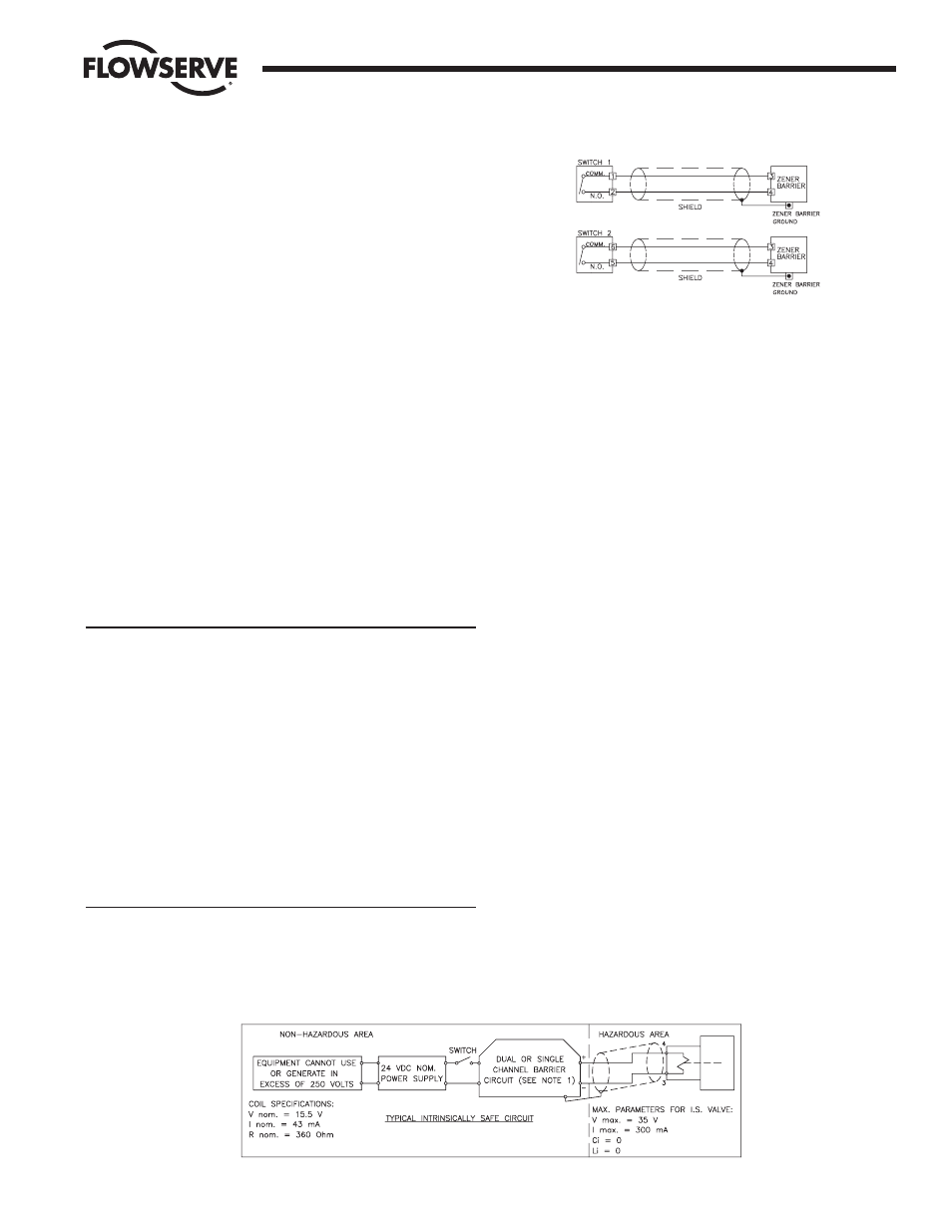
B. ELECTRICAL CONNECTION:
The intrinsically safe versions of the ACCESS I and ACCESS M will
be intrinsically safe when connected through CSA Certified zener
barriers rated 28 volts DC maximum, 300 ohms minimum (for
SW-1 and SW-2 only; refer to paragraph 4 of this section for
intrinsically safe wiring of solenoid), as shown in the wiring
diagrams (Figure 2) below.
IMPORTANT: Shielded cable must be used for each intrinsically
safe circuit (Switch circuits and solenoid circuit) and for zener
barriers, the shield must be connected to a zener barrier ground.
1. The “standard” mounting configuration of the 39 actuator to
the valve is in-line, fail-closed. In this configuration, SW-2, as
described in the wiring diagram and part 3, will give
indication when the actuator is in the closed position, or CW
limit of rotation. SW-1 gives indication of the open position,
or CCW limit of rotation (refer to the appropriate wiring
diagram in figure 2).
NOTE: The CW or CCW rotation of the actuator shaft is
determined when viewing the actuator from the nameplate
side of the actuator while being able to read the nameplate
from left to right.
2. Fail open configuration for sizes 10–20 may be obtained by
either inverting the actuator, using in-line coupling, or
mounting the actuator cross-line. For sizes 25 and larger the
coupling (including valve ball and stem) must be indexed 90°
to the actuator shaft. Refer to Installation Section D.6.b. In
these cases, SW-1 and SW-2 indication will be reversed from
the above but actuator rotation will vary, depending on which
fail-open mounting is used, and wiring shall be done per the
appropriate wiring diagram in figure 3.
Flow Control
Worcester Controls
Figure 1
Figure 2