Actuator disassembly, Worcester controls – Flowserve 10 ACCESS I Worcester Controls User Manual
Page 9
WCAIM2028
10, 15, 20 ACCESS I and 10-40 Access M 39 Actuators Intrinsically Safe
9
ACTUATOR DISASSEMBLY
1. Disconnect the air supply and electrical service to the actuator.
2. Remove the actuator and its mounting bracket from the valve.
(See Caution note.)
CAUTION: Ball valves can trap pressurized media in the cavity.
Isolate the piping system in which the actuator/valve assembly
is mounted and relieve any pressure on the valve. For all the
valves listed in Installation Section D, the actuator bracket can
be removed without loosening or removing any valve body
bolts.
3. Remove the actuator bracket from the actuator to begin repair.
(Note orientation of removed bracket for easy reassembly.)
4. It is not necessary to remove the control block (7A) or air
connection block (7B) to rebuild actuator. However, if it becomes
necessary to remove the block, begin by removing the block bolts
(7D). Use care to retain the block gasket (9A, 9B or 9C).
5. Each end cap (5A & 5B) is aligned onto the body (1) over a
“foolproof pin”. This ensures that the end caps can only be
assembled to their respective end of the actuator. Remove all four
metric screws (5C) from and remove both end caps. Remove the
two bearings (6A) and O-rings (15A and 15B) from each end cap.
CAUTION: If the actuator is a spring-return model, first
remove two end cap screws diagonally opposite each other,
then lubricate the threads and under the head. Replace the
screws and repeat procedure for the other two screws. Do this
for each end cap, as this will aid reassembly. Now uniformly
loosen all four end cap screws on each end cap two to three
turns at a time, in sequence, to relieve preload of the springs.
On larger actuators with springs use caution when removing
end caps. End cap screws are long enough to allow springs to
relieve before disengaging.
After the screws are removed, gently pry off each end cap, being
careful not to damage the end cap O-rings.
6. The two piston guide rod (4) assemblies can now be removed
from each end of the body and disassembled by removing the
piston set screws (12). Do not interchange piston guide rods (4)
and their respective piston (3). For sizes 10–20 Rev. R6 actuators,
each guide rod and piston may be press fitted together (do not
use set screws) and cannot be disassembled. (To assist
reassembly, mark the body with a line on the side from which the
guide rod using the through-hole is removed). Remove all O-rings
(15B and 15C) and bearings (6B) from pistons (3).
7. The shaft (2A) on sizes 10–20 can only be removed after piston
assemblies are taken out. Remove the position indicator (17) (if
any), the shaft clip (15F) (not a reusable part!) (see Note) and the
stainless steel washer from the top of shaft. Then remove the
shaft through the larger opening in the bottom of the body. The
top bearing (15G) and the O-ring (15D) can now be removed.
Remove the two stainless steel washers (10–35 sizes only) and
thrust bearing (10) from the top of the shaft, the O-ring (15E),
and bearing (15H) from the bottom end.
NOTE: For size 40 model, only a single stainless steel washer is
used and thrust-bearing (10) is not used.
Sizes 25-40 have an anti-ejection ring (15J). This ring does not
have to be removed and it may or may not be included in repair
kits.
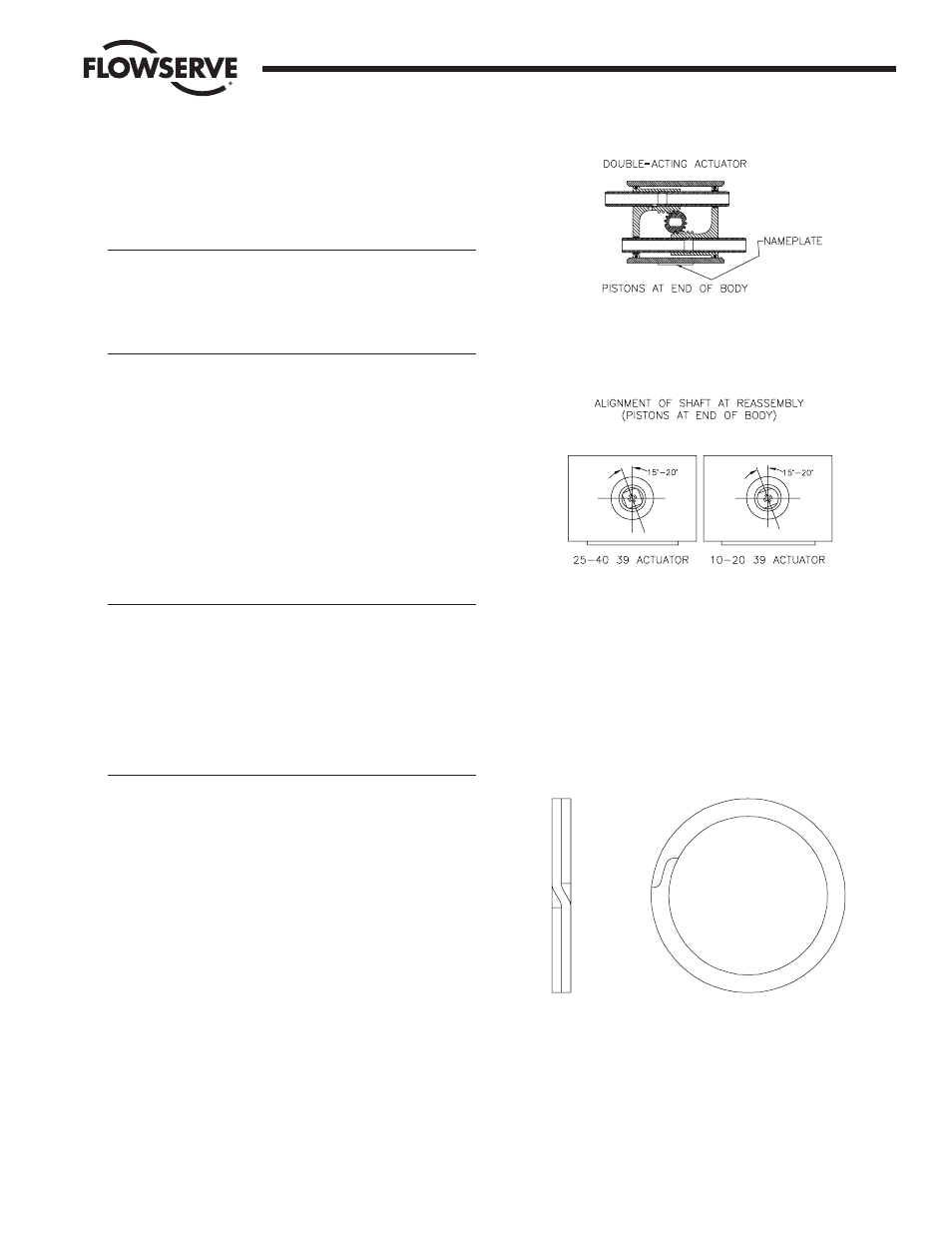
NOTE: Some actuators may be using a spiral ring type shaft clip
as shown below.
To remove this clip, engage the lower end of the ring with a flat blade
screwdriver. Using another flat blade screwdriver push the top end of
the clip in the opposite direction. As the clip I.D. expands lift the clip
from the shaft. The installation of a new clip would be the above steps
in reverse and ensuring that the edges of the clip are properly seated
in the shaft groove.
Flow Control
Worcester Controls
Figure 6
Figure 7
IMPORTANT: Note the relative location of the shaft teeth and the
piston assembly’s rack teeth. The above figure is viewed when
looking at the top of the actuator.
IMPORTANT: Align gear teeth on the shaft per Figure 6.