Calibration – Flowserve PMV Valve Control System User Manual
Page 10
Manual F5
– 10 –
Calibration
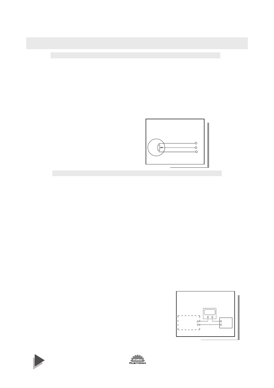
Potentiometer
1.
Make electrical connections to terminals 7,8 and 9. Check that the
potentiometer is connected to connector C on the printed circuit board.
2.
Stroke the actuator to check direction of travel indicated by the potentio-
meter. To change direction of travel, swap wires at terminals 7 and 9.
3.
Stroke the actuator to the position where the minimum potentiometer
resistance is desired.
4.
Adjust the potentiometer output reading to approx. 50 Ohm by
rotating gear wheel 2 with special tool F5-22 or tip of a screw driver
placed in one of the slotted holes.
5.
Stroke the actuator to desired
maximum resistance position and
check reading.
6.
Repeat steps 3-5 if necessary to
obtain desired resistance change.
7. Set switches or install frontcover.
Potentiometer
7
8
9
Power
Supply
24 VDC
+
-
4-20 mA position transmitter
8
9
-
+
Display
4-20 mA
+
-
4-20 mA
position
transmitter
5.
Adjust the output signal 4,0 mA with potentio-
meter P2. LED will illuminate when out put is 4
mA (
±
1%) or less. Stroke actuator to the desired 20
mA position and adjust the output to 20,0 mA with
potentiometer P1. LED will illuminate when out
put is 20 mA (
±
1%) or more.
6.
Stroke actuator again, check and adjust 4 mA and
20 mA readings. Install front cover or set switches
first, as follows:
4-20 mA position transmitter
1.
Set direction of rotation by placing potentiometer jumper in location A or
B. (Location A for counter clockwise CCW valve/actuator rotation (Direct),
location B for clockwise CW valve/actuator rotation (Reverse).
2.
Set jumper X to the desired valve rotation angle, for 30 deg or 45 deg
rotation choose position 30,
For 60 deg or 90 deg rotation choose position 90, for 180 deg rotation choose
position 30 and for 270 deg rotations choose position 90.
For 30
°
deg - 45
°
deg choose pos 30.
3.
Make electrical connections according to wiring diagram. Power supply
should be >9 to <28 VDC (24 VDC recommended).
4.
Connect a 4-20 mA meter to testoutlet 1. Adjust potentiometer P1 20
revolutions CW & P2 20 revolutions CCW. Stroke actuator to the desired 4
mA position and check that current deflection is correct. Rotate gear wheel
2
with tool F5-22 or tip of a screw driver placed in one of the slotted holes
until minimum valve is reached.