Flowserve PMV Valve Control System User Manual
Page 9
Manual F5
– 9 –
Connections
WARNING!
Units installed in hazardous locations must have proper agency approvals
and be installed according to installation drawing F5-2-4-9516.
Conduit entries are PG13,5 (M20) or NPT 1/2“
Make electrical connections according to wiring diagrams and tighten cable
glands. Terminals are 2.5 mm
2
(AVG 14) screw terminals.
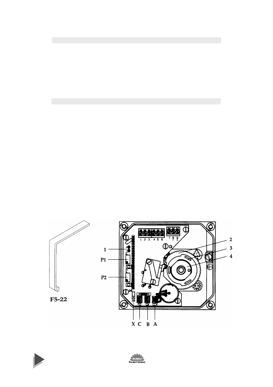
Adjustments
CAUTION! Moving parts – risk of injury.
The cams/gear wheel are secured in position by friction provided from the
cam/shaft assembly. To adjust switches and/or position transmitter, rotate
gear wheel 2 and cams 3 to desired position using tool F5-22 or tip of a screw
driver that fits snuggly in one of the slotted holes. Start calibration procedure
by adjusting position transmitter first, then continue with the lower switch
and complete with the upper switch.
If cams exhibit high stiction, rotate them back and forth rapidly several times.
Do not adjust nut 4 or lubricate cams, call PMV for assistance.