Wiring, Fig. 11 – Flowserve NRG 16-38S User Manual
Page 18
18
1. Use flexible cable to connect the power supply. Use a separate flexible screened
cable, min. conductor size 1.5 mm² for connecting the signal output.
2. Undo screws and remove housing cover . The arrow on the name plate points
towards the cover, fig. 5.
3. Remove terminal strip from circuit board.
4. Undo union nuts of the cable gland and pull connecting cables for power supply
and signal output through separate cable glands.
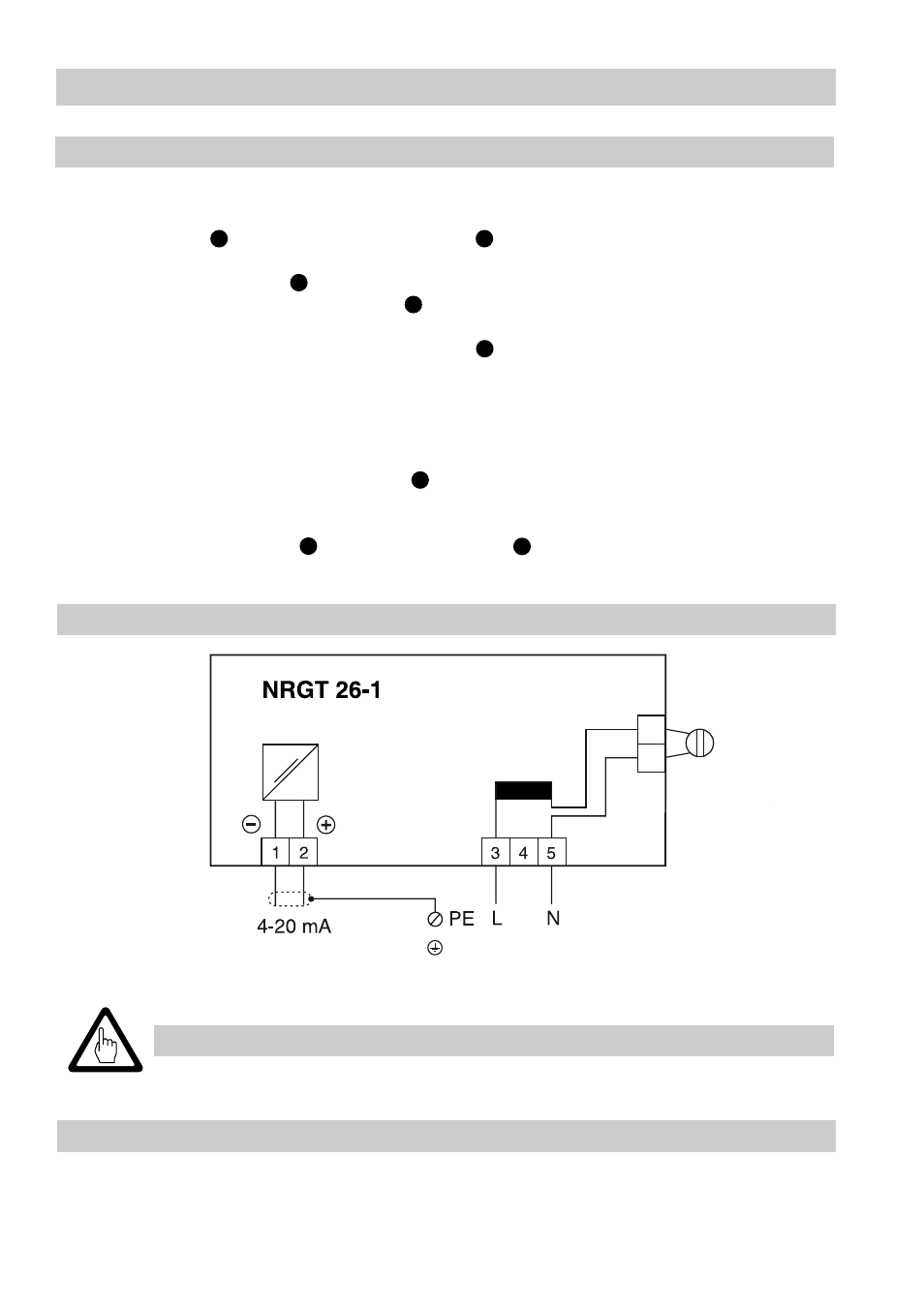
5. Connect terminal strips and PE connection according to wiring diagram. Make
sure that the screen of the signal cable is also clamped under the earthing screw
for the PE connection.
6. Plug in terminal strip. Attention! The following displacements of base-insulated
cables are not allowed: power cables in low voltage area; signal cables in mains
voltage area.
7. Retighten union nuts of cable gland . Use plug supplied with electrode to seal
unused cable glands.
8. Configure level electrode (see “Basic Settings”, “Commissioning”).
9. Replace housing cover and fix it with screws , making sure that the cover
gasket fits properly.
■
Fuse supply cables 250 mA (slow-blow).
Wiring
– continued –
Tools
Attention
Wiring Diagram
■
Screwdriver for cross head screws, size 1
■
Screwdriver for slotted screws, size 2.5, completely insulated according to
VDE 0680-1
G
I
H
H
R
S
I
G
NRGT 26-1
Fig. 11
Earthing screw
in housing
Mains
Thermal fuse
max. load