Reliminary operational check, Ounting – Flowserve 103 Smart Multi-Port IPS Wireless User Manual
Page 11
IPS WIRELESS SELD-103 ENGLISH 26999976 11-13
Page 11 of 20
flowserve.com
6.2 Preliminary operational check
After unpacking and before field installation,
perform the following operational check on the unit:
1. Ensure the magnetic set screw (at the bottom
of the base) is removed. This keeps the unit
powered down during the installation process.
2. Place SELD-103 unit in vertical position with a
clear line of sight to and close to (<10ft) the
receiver. If only using the VB-103-TAM or VB-
103-VIS accessories, install the appropriate
accessory on the SELD-103 unit (VB-103-TAM
on port 6 and VB-103-VIS on port 5).
3. Insert sensor cable(s) into the proper port(s).
4. Install the magnetic set screw (in the bottom of
the base) to power up the unit.
5. Ensure the receiver is receiving data from the
unit. Let the VB-103-TAM log data for a few
minutes and confirm appropriate light operation
of the VB-103-VIS unit as applicable.
6. If applicable, disconnect VB-103-TAM and use
IPS Dock to confirm accurate data has been
logged (refer to IPS Dock user instructions for
how to do this).
7. Remove magnetic set screw (bottom of base)
to power down unit.
8. Disconnect sensor cable(s) from SELD-103
port(s).
In case of issues with powering up the unit, refer to
section 9 Trouble-Shooting Guide.
6.3 Mounting
Each unit should be clear of physical obstructions
to the receiver and/or repeater(s) in order to
maintain consistent communications.
The SELD-103 is designed to be mounted in a
vertical position and should only be mounted in a
horizontal position with approval from the factory.
Ensure the SELD-103 is not subjected to excessive
vibration unless a routine maintenance program
includes verification of associated connections.
The SELD-103 unit should be installed near but not
on process equipment being monitored.
Mount the SELD-103 unit before connecting any of
the sensor cables.
6.3.1 Pole or Unistrut-Mounted Option
With this option the SELD-103 unit can be mounted
to either a vertical or horizontal pole or unistrut.
Start by bolting the SELD-103 unit to the mounting
bracket and then bolt the bracket to the appropriate
holes on the mounting adapter (see figure below).
Lastly, attach the other end of the mounting
adapter to the pole (using a U-bolt) or unistrut
(using bolting).
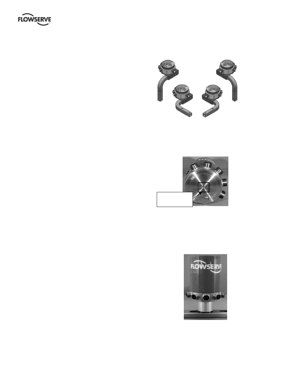
Figure 8: Pole or unistrut mounting options
6.3.2 Magnetic Mount Option
Insert set screw into bottom of SELD-103 unit and
tighten.
Figure 9: Magnetic mounting option set screw
location
Next, take magnetic mounting base and thread
onto the exposed set screw from the bottom of the
SELD-103 unit. The magnetic mounting base (with
the SELD-103 unit attached) can now be attached
to any metal structure in a vertical position.
Figure 10: Sample SELD-103 unit with
magnetic mount option installed on unistrut
Magnetic mount set
screw installation
location