5 recommended spare parts – Fluke Biomedical 07-440 User Manual
Page 15
Maintenance & Calibration
Lamp Replacement
3
3-5
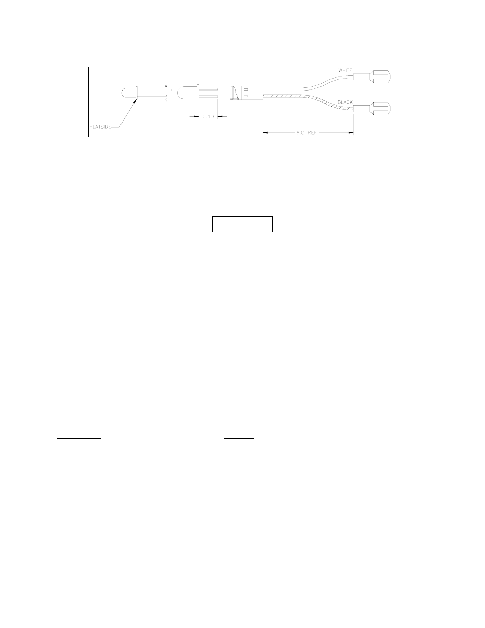
Figure 3-1. LED/Socket Assembly
5. Replace with a new LED, being careful to tighten the LED/Aperture Holder screw only enough to
hold the LED Socket Assembly in place. When the LED is properly positioned vertically, it will
almost touch the aperture in the holder.
6. Return the light table top to its position on the board and fasten it in place.
This instrument contains CMOS Integrated circuits.
No service should be attempted unless by a
qualified technician thoroughly familiar with CMOS
devices. Static charges normally present in a dry
atmosphere or leakage current in soldering irons or
other non-grounded tools can instantly destroy
CMOS integrated devices. Do not attempt to
remove or replace any IC sockets without
observing anti-static and leakage current
precautions.
3.5 Recommended Spare Parts
Recommended spare parts are listed below. Table 3-1 provides a parts lists for the Main Board Assembly
and the RS-232 Interface Board Assembly, respectively. Figure 3-1A and 3-1B (RS-232C Interface Board
Schematic Diagram), and Figure 3-2 (RS-232C Interface Board Component Layout) are provided for
reference.
Description Part
No.
Table Lamps, #37
680011
Measurement LED
65-158
LED Socket Assembly
112327
O-ring, Light Seal
0960013
Aperture Set, l ea. 1, 2 & 3 mm
112023
Fuse for 115 VAC, 1 A, AGC,
760001
Fuse for 230 VAC, 0.5 A, AGC,
760004
WARNING