2 layout – Foxconn Quantumian1 User Manual
Page 11
Advertising
1
4
1-2 layout
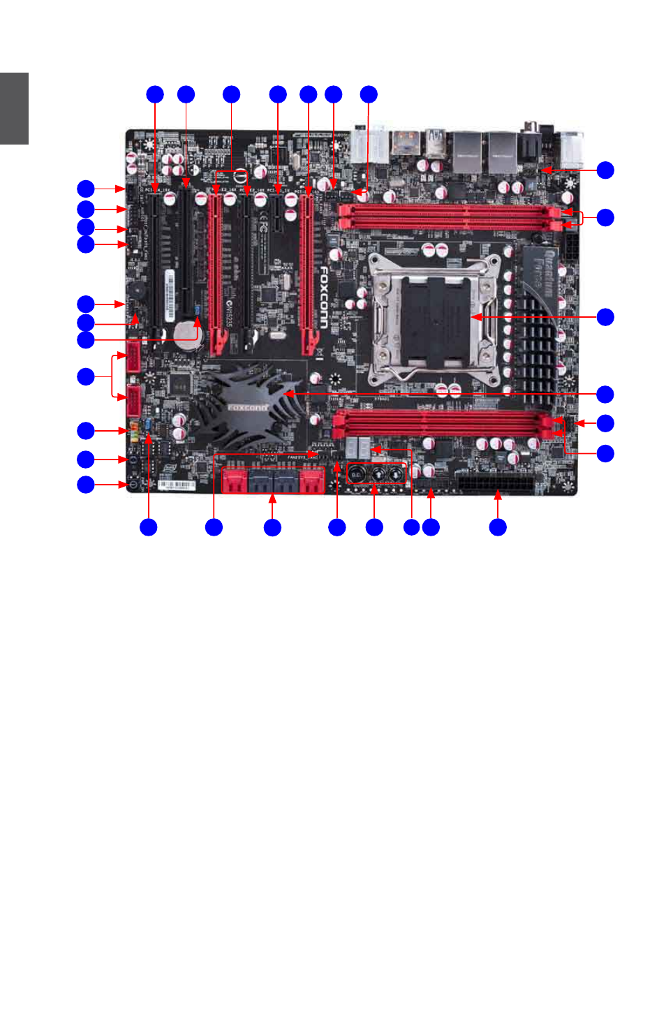
Note : The above motherboard layout is for reference only, please refer to the physical
motherboard for detail.
1. SYS_FAN Header
2. FAN Header
3. PCI Express x16 Slot
4. PCI Express x1 Slot
5. PCI Slot
6. CD_IN Connector
7. Front Audio Connector
8. SPDIF_OUT Connector
9. Speaker Connector
10. Clear CMOS Jumper
11. VBAT_Discharge Jumper
12. Front USB 2.0 Connector
13. Front Panel Connector
14. Reset Button
15. Power On/Off Button
16. BIOS-SELECT Jumper
17. SATA Connector
18. OC Button
19. Debug LED
20. Front USB 3.0 Connector
21. 24-pin ATX Power Connector
22. DDR3 DIMM Slot
23. CPU_FAN Header
24. Chipset: Intel® X79
25. LGA2011 CPU Socket
17
25
7
2
6
1
8
20
21
16
3
9
3
12
10
22
22
23
24
13
11
5
4
3
2
1
1
8
14
15
18
19
Advertising