Foxconn P4M8907MA-KRS2H User Manual
Page 11
Chapter 1 Product Introduction
4
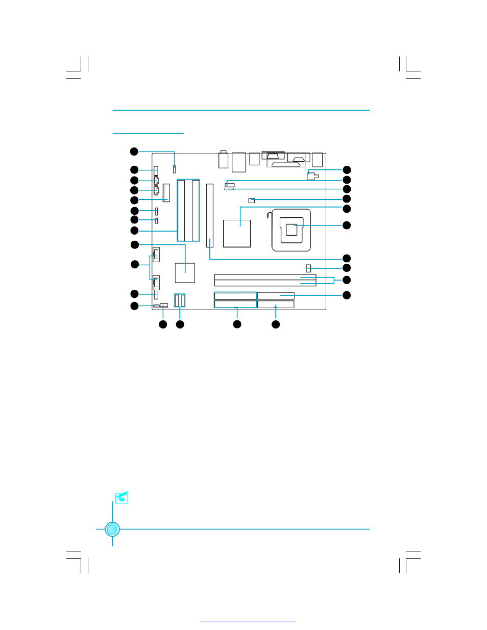
Motherboard Layout
1. S/PDIF OUT Connector
2. Front Audio Connector
3. CD_IN Connector
4. AUX_IN Connector
5.PCI Express X1 slot
6.Speaker Connector
7. Clear CMOS Jumper
8. PCI Slots
9. South Bridge: VIA VT8237R Plus
10. Front USB Connectors
11. Front Panel Connector
12. BIOS Write Protect Jumper
13. System Fan Connector
14.SATA Connectors
15.HDD Connectors
16.FDD Connector
17.24-pin ATX Power Connector
18.DDR 2 memory Slots
19.CPU Fan Connector
20.PCI Express X16 slot
21.CPU Socket
22.North Bridge: VIA P4M890
23.System Fan Connector
24. IrDA connector
25.COM2 Connector
26.4-pin ATX 12V Power Connector
Note: This motherboard layout is provided for reference only; please refer
to the physical motherboard.
23
20
21
19
18
17
16
2
3
9
10
11
22
1
12
4
8
6
5
24
25
7
26
13
14
15
PDF 文件使用 "pdfFactory" 试用版本创建