Fronius Transceiver Card User Manual
Page 19
5
EN-US
Installing Wireless Transceiver Card And Wireless
Transceiver Box
General
WARNING! Mains voltage can be deadly. The connection area should only be
opened by a licensed electrician after being disconnected from the mains
power.
WARNING! An electrical shock can be fatal. Danger from mains voltage and
DC voltage from solar modules. Plug-in cards should only be inserted when
the FRONIUS inverter
-
is disconnected on the power side (AC-side)
-
is disconnected from the solar module (DC-side)
When inserting the plug-in card:
1.
Set the FRONIUS inverter to Standby mode
2.
Disconnect the FRONIUS inverter from the AC and DC sides
3.
Open connection area or remove housing cover (as per the operating instructions of
your FRONIUS inverter)
Insert Wireless
transceiver card
into the FRONIUS
inverter
NOTE Radio quality may be affected in systems with an additional personal
display. The installation spacing between the antennas must be a min. of 2 m
(6.5 ft.).
Important The mounting bracket is part of the antenna. Only fit the antenna to the
mounting bracket supplied with the antenna.
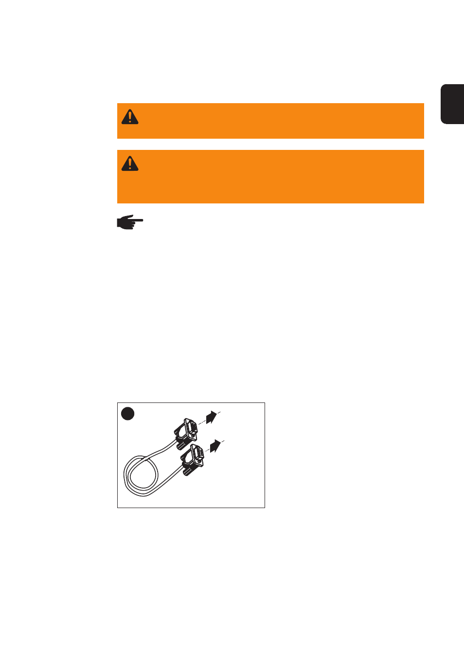
Connecting
Wireless Trans-
ceiver Card to the
DatCom Card
After inserting the Wireless transceiver card, connect to the DatCom card (e.g. Datalog-
ger card) using a serial extension cable (1:1 cable - included with delivery).
1
1
2