Geist SA1-01003LNB User Manual
Page 2
GM1165
REV DATE: 05/2014
SA1-01003LNB Installation Procedures
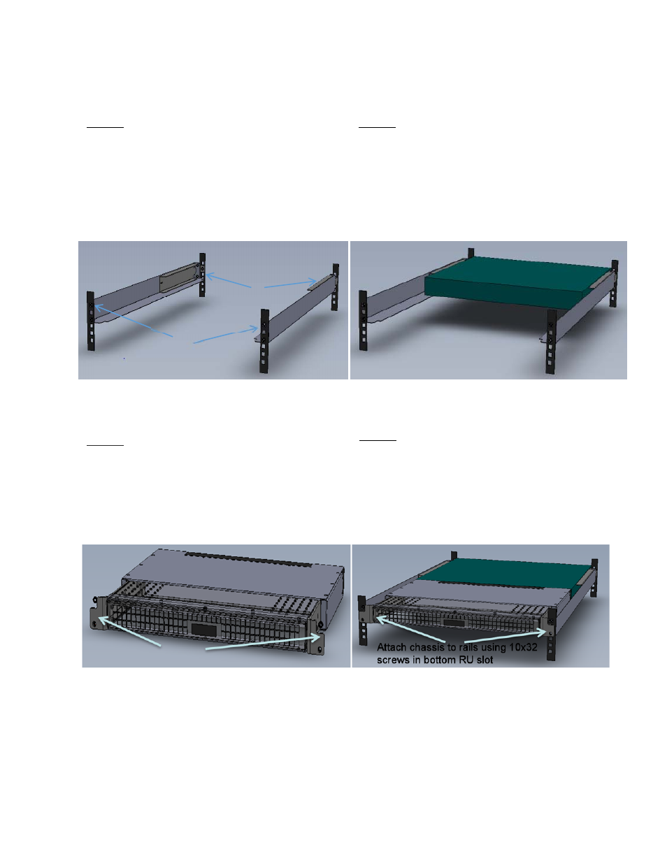
STEP 1: The channels will be mounted to the rack
using 10x32 provided screws. The rack front two
channels will have two screws in each. The upper
slot is for the channel and the bottom slot is for the
chassis when installed. The rack rear will mount
using one 10x32 screw in each channel if the
channel extension is used or two 10x32 screws if
the channel extension isn’t required.
STEP 2: Once the channels are in place, slide the
data switch on the channels and attach to the rear
rails. Cage nuts may be required to complete this
step.
STEP 3: Before installing the chassis/extender the
unit must be extended to the longest length. This is
done by pulling the tabs on the chassis away from
the extender. The cables that attach to the back of
the data switch must be in place to route through the
brush strips when the chassis/extender is pushed
into place.
STEP 4: With the data switch cables are in place,
push the chassis/extender until it’s tight against the
data switch and the front rail. Make sure that the
cables are routed correctly and there is no gap
between the data switch and chassis/extender.
Attach the chassis to the front rail using two 10x32
provided screws. Installation complete.
Pull tabs to extend.
Attach channels to rails
using 10x32 screws in top
RU slot
Attach channels to rails
using 10x32 screws in
middle RU slot