Grip Factory Munich GF-16 User Manual
Page 42
GF-16 Crane System Instruction Manual
Page: 41
Version 15
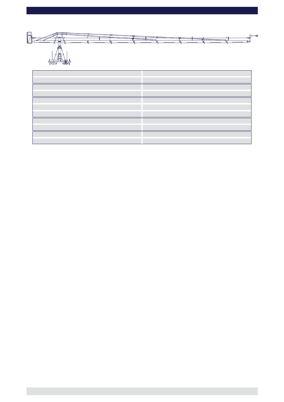
Front extension arms required
8 x 200 cm / 6' 6”
Rear extension arm required
1 x 192 cm / 6' 3”
Lift range
2548 cm / 83’ 7”
Maximum Euro-adapter height
1531 cm / 50' 2”
Lift capacity (working load) camera + accessories
60 kg / 132 lbs
Counterweight required for max. load
1362 kg / 2996 lbs
Counterweight required to balance empty arm
938 kg / 2063 lbs
Crane weight (excluding dolly and weights)
927 kg / 2044 lbs
Dolly weight (unit weights see page 46)
244 kg / 536 lbs
Arm reach (pivot to camera head mount)
1681 cm / 55’ 1”
Length of rear end (pivot to outside of bucket)
278 cm / 9’ 1”
Continue from § 12, page 6
13. Connect the 200cm / 6’ 6” extension number 2 to extension number 1. Slip the
connection flanges into each other and secure with the provided safety pin.
Note: Section 2 must be supported by a suitable support stand or rostrum.
Tip:
To avoid the sections jamming or getting stuck make sure that the sections
are joined parallel. Using a small amount of lubricant also helps. We suggest
rubbing the joints with an oiled rag prior to assembly.
14. Connect the 200cm / 6’ 6” extension number 3 to extension number 2. Slip the
connection flanges into each other and secure with the provided safety pin.
Note: Move the support stand or rostrum to support section number 3.
15. Connect the 200cm / 6’ 6” extension number 4 to extension number 3. Slip the
connection flanges into each other and secure with the provided safety pin.
The “Rigging Harness Assembly” is described on page 9. After reading and
following the instructions, please proceed as follows.
16. Connect 2 turnbuckles to the bottom connection on the front side of the rigging
harness. Ensure that the locking pins are inserted fully.
17. Connect 2 standard rigging rods to the turnbuckles on the front side of the rigging
harness. Ensure that the locking pins are inserted fully.
18. Connect 2 more standard rigging rods to the first rigging rods. Ensure that the locking
pins are inserted fully.
19. Connect 2 more standard rigging rods to the second rigging rods. Ensure that the
locking pins are inserted fully.
20. Connect 2 Rigging Support Brackets to the Rigging Rod Connections on section 3.
Ensure that the locking pins are inserted fully.
21. Connect a Rigging Rod Connector to each of the third Rigging Rods ensuring that the
locking pins are inserted fully. Fit the Rigging Rod Connectors into the Rigging
Support Brackets as shown on page 10.
22. Connect 2 standard rigging rods to the Rigging Rod Connectors and in turn to the to
the rigging connectors on section 4. Ensure that the locking pins are inserted fully.
23. Hand tighten the rods by turning the turnbuckles until the rods are taut, then secure
the turnbuckles with the locking nut as seen on page 9.