Hypertherm HT2000 Water Muffler User Manual
Page 17
Page 2-8
INSTALLATION
HT2000/MAX200 Water Muffler
Instruction Manual
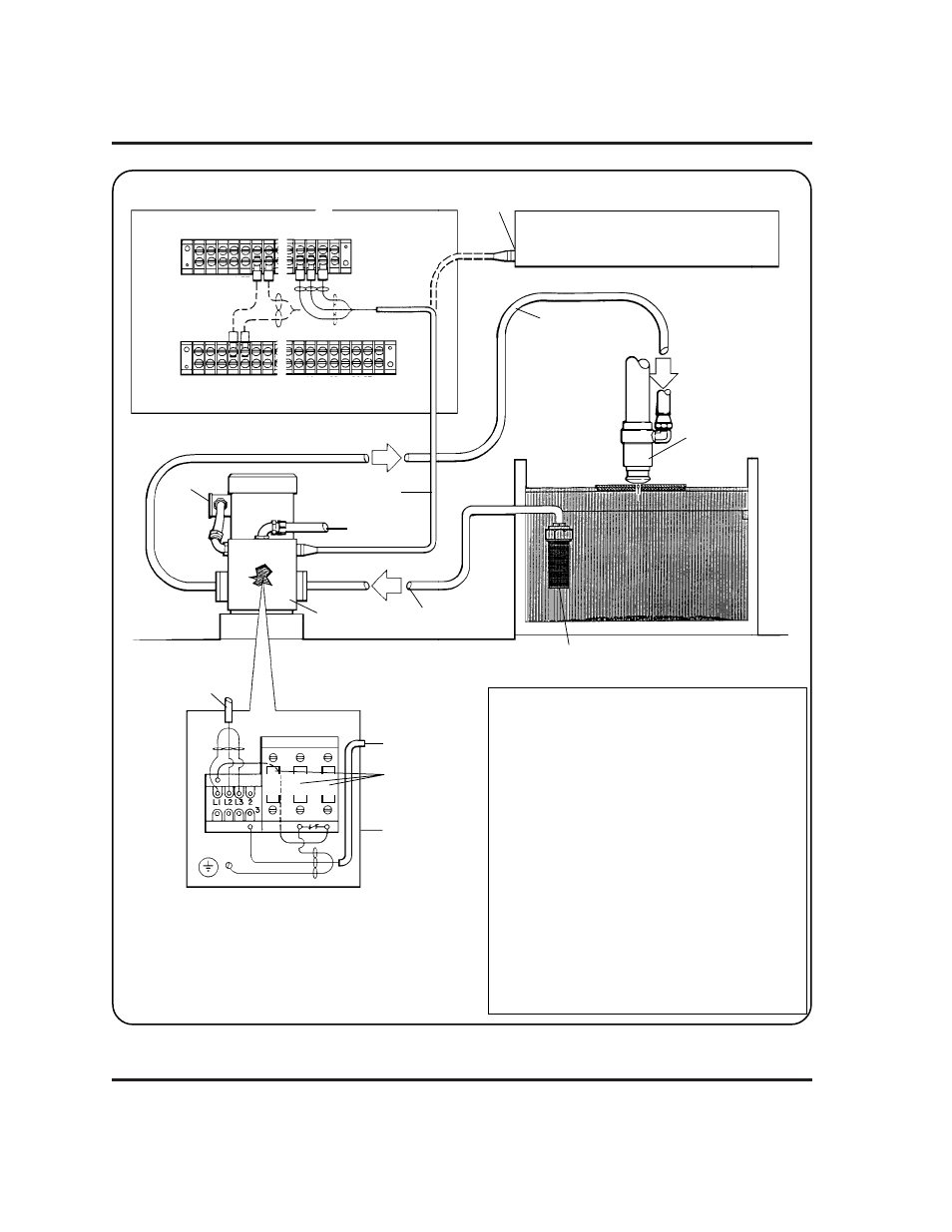
Figure 2-3 Water Muffler System Interconnection Diagram
7-96
CONNECTIONS FOR
MAX200 W/O RHF
CONNECTIONS
FOR MAX200/RHF
MAX200
TB4
TB3
61 60 78 79 80 81
HT2000
120 VAC CONTACTOR
RELAY POWER
WATER TO
NOZZLE ASSEMBLY
INPUT POWER
PUMP
WATER TO PUMP
CONTACTOR BOX
INPUT POWER
DETAIL OF
CONTACTOR BOX
120 VAC CONTACTOR
RELAY POWER
FILTER STRAINER
WATER MUFFLER
1X10
34 35 76 77
82 83 84 85 86 87
302
303
SHIELD
NOZZLE ASSEMBLY
34 35 76 77 88 89
61 60 80 81
82 83 84 85 86 87
LINK BOX
CONTACTOR
HEATER LOCATION
Notes:
The 240/480V water muffler pump is shipped to
operate at 480V. The 380/415V pump is shipped
to operate at 380V. See tag on the pump to link
for alternate voltages. Link box is located on the
pump housing (see drawing).
The 240/480V and 380/415V pumps are shipped
with two sets of 3 contactor heaters located in the
contactor box. See the chart below to determine
which heater to use.
Heater Hypertherm
Voltage Amps Label
Part No.
240V (230V)
6.06
W45
003170
380V
3.00
W38
003029
415V
3.00
W38
003029
480V (460V)
3.00
W38
003029
600V (575V)
2.45
W36
003171