Hypertherm SensorOHC User Manual
Page 16
12
Sensor OHC Operation and Set Up Guide
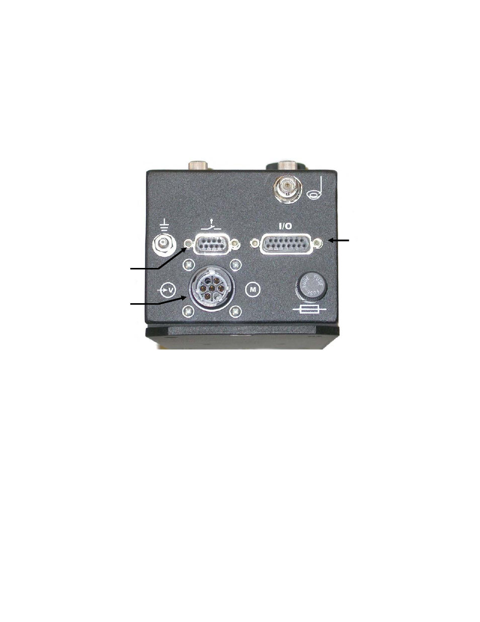
Connectors
Wire the unit as shown with reference to the following figures. A standard mating connector kit is
available which provides the mating 9 pin & 15 pin “D” type connectors and the 7 pin circular
power connector (CONN-0141). Also available for drop-in demonstration purposes is a connector
conversion kit that will adapt the unit to AR300/100 style connectors (CABL-0163). It is
recommended that you use the AR300/100 conversion kit for demonstration purposes only. Use
of the plastic housings on the AR300/100 style connectors does not allow for proper cable
shielding. Improper cable shielding can result in severe electrical interference problems.
Power Connections
All power connections are made to the 7 pin circular connector. When connecting to the motor,
ensure that the motor polarity is such that if pin 2 is positive with respect to pin 5 the slide will
move in the UP direction. The 24 Vac power source is connected between pins 3 and 6. Pin 4 is
connected internally to the grounding stud on the enclosure and the ground stud should be
connected to the machine chassis.
24VAC Input / Motor Pinout
7 Pin Amp Connector
Pin Description
3
24VAC
6
24VAC Return
4
Ground
2
Motor
5
Motor
Power & Motor
Limit Switches
Control Interface