Calibration procedure – Hypertherm SensorOHC User Manual
Page 22
18
Sensor OHC Operation and Set Up Guide
Calibration Procedure
Calibration Instructions
1) Install the torch and sensor ring with torch tip aligned with the bottom edge of the sensor. Ensure that
all DIP switches are correctly set for cable length, lifter speed, and sensitivity, and max motor current
(see DIP Switch Set Up).
2) Set the unit for Manual operation and then apply power to unit.
3) Position the sensor ring above the plate. Use the UP/DOWN switch to raise the sensor ring at least
100 mm or 4 inches above the plate.
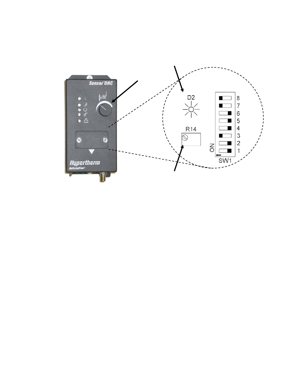
4) Remove the Calibration Panel and adjust the CALIBRATION POT. When adjusting the calibration,
check that nothing abnormal is in the vicinity of the sensor ring. This includes the person who is
performing the calibration. The CALIBRATION LED should remain flashing even when the screwdriver
is removed from the CALIBRATION POT.
If the CALIBRATION LED is OFF, then rotate the pot clockwise (CW) until the LED is flashing.
If the CALIBRATION LED is ON, then rotate the pot counter clockwise (CCW) until the LED is flashing.
5) Check the Calibration - Set the Height Set Point to MAX and place the unit into the AUTO mode. The
sensor should be stable about 1 inch or 25mm above the plate. Adjust the Height Set Point to MIN.
The sensor should now be about 1/10 inch or 2.5 mm above the plate.
NOTE: The RJ45 connector under the calibration panel is not a network connection. It is a proprietary
connector and is for the use of authorized service personnel only.
Calibration Pot
Calibration LED
Height Set Point