IBASE MB941 User Manual
Page 24
INSTALLATIONS
20
MB941 User’s Manual
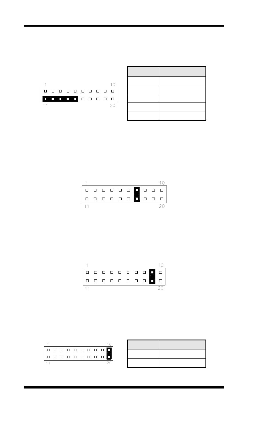
Power LED: Pins 11 - 15
The power LED indicates the status of the main power
switch.
Pin #
Signal Name
11
Power LED
12
No connect
13
Ground
14
No connect
15
Ground
ATX Power ON Switch: Pins 7 and 17
This 2-pin connector is an “ATX Power Supply On/Off
Switch” on the system that connects to the power switch on
the case. When pressed, the power switch will force the
system to power on. When pressed again, it will force the
system to power off.
Reset Switch: Pins 9 and 19
The reset switch allows the user to reset the system without
turning the main power switch off and then on again.
Orientation is not required when making a connection to this
header.
Hard Disk Drive LED Connector: Pins 10 and 20
This connector connects to the hard drive activity LED on
control panel. This LED will flash when the HDD is being
accessed.
Pin #
Signal Name
10
HDD Active
20
5V