IBASE MB967 User Manual
Page 22
Advertising
INSTALLATIONS
22
MB967 User’s Manual
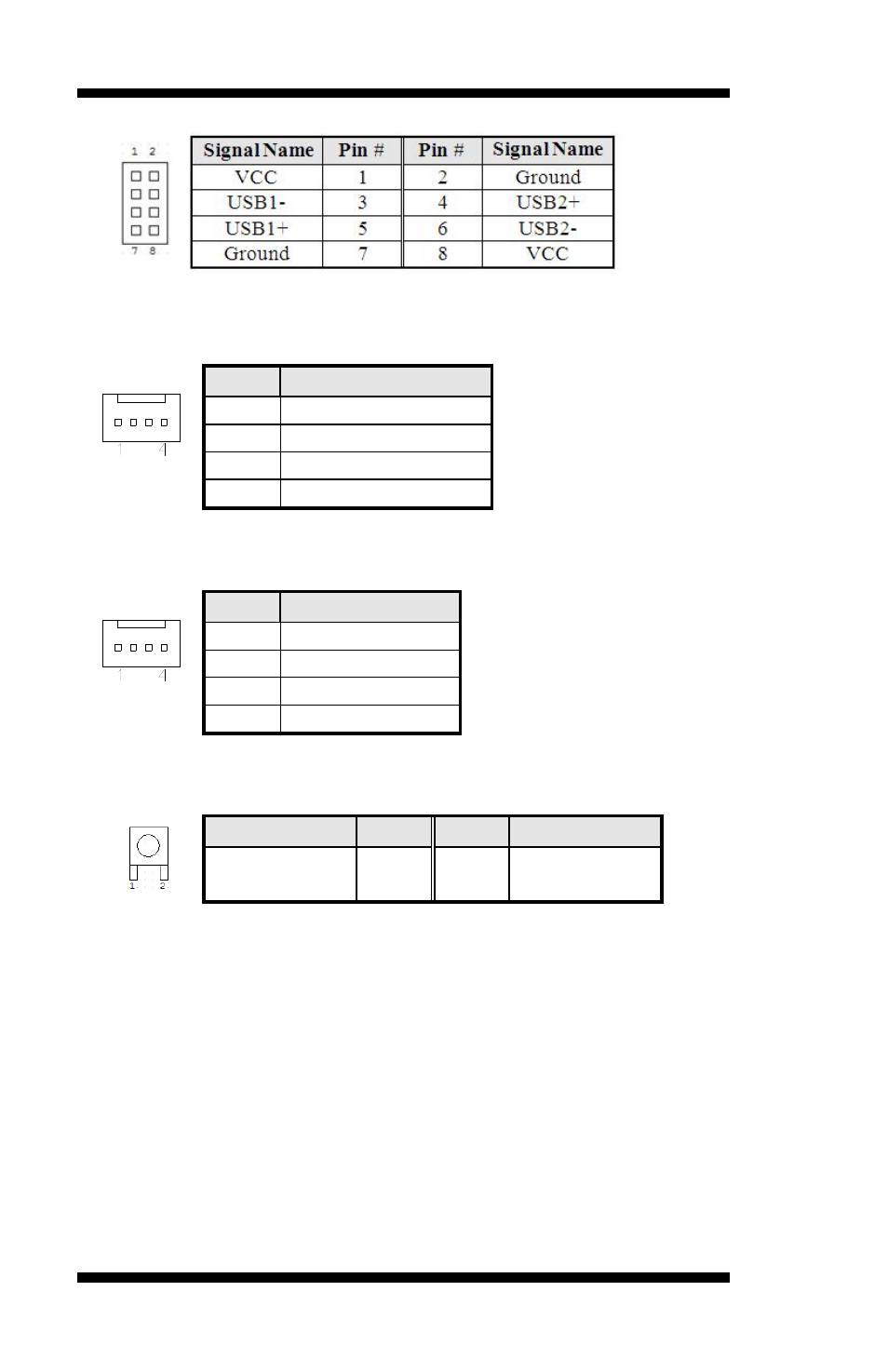
J20, J21: USB 2.0 Pin Header
FAN1, 2, 3: System Fan Power Connector
FAN1/2/3 are 4-pin headers for System fan power.
Pin #
Signal Name
1
Ground
2
+12V
3
Rotation detection
4
Control
CPU_FAN1: CPU Fan Power Connector
Pin #
Signal Name
1
Ground
2
+12V
3
Rotation detection
4
Control
SW1: Software reset button
Signal Name
Pin #
Pin #
Signal Name
GND
1
2
PCH
GPIO7
IO Base:
Read IO 0x500 and set bit 7 to “1” (Enabled GPIO function)
Read IO 0x504 and set bit 7 to “1” (GPIO act as GPI )
Read IO 0x50C and check the bit 7 (Control Pin)
Note: SW3 is controlled by GPIO only.
PCIE1: PCI-e x8 Golden Finger 1
PCIE2: PCI-e x8 Golden Finger 2
Advertising