IBASE IB945 User Manual
Page 16
INSTALLATIONS
12
IB945 User’s Manual
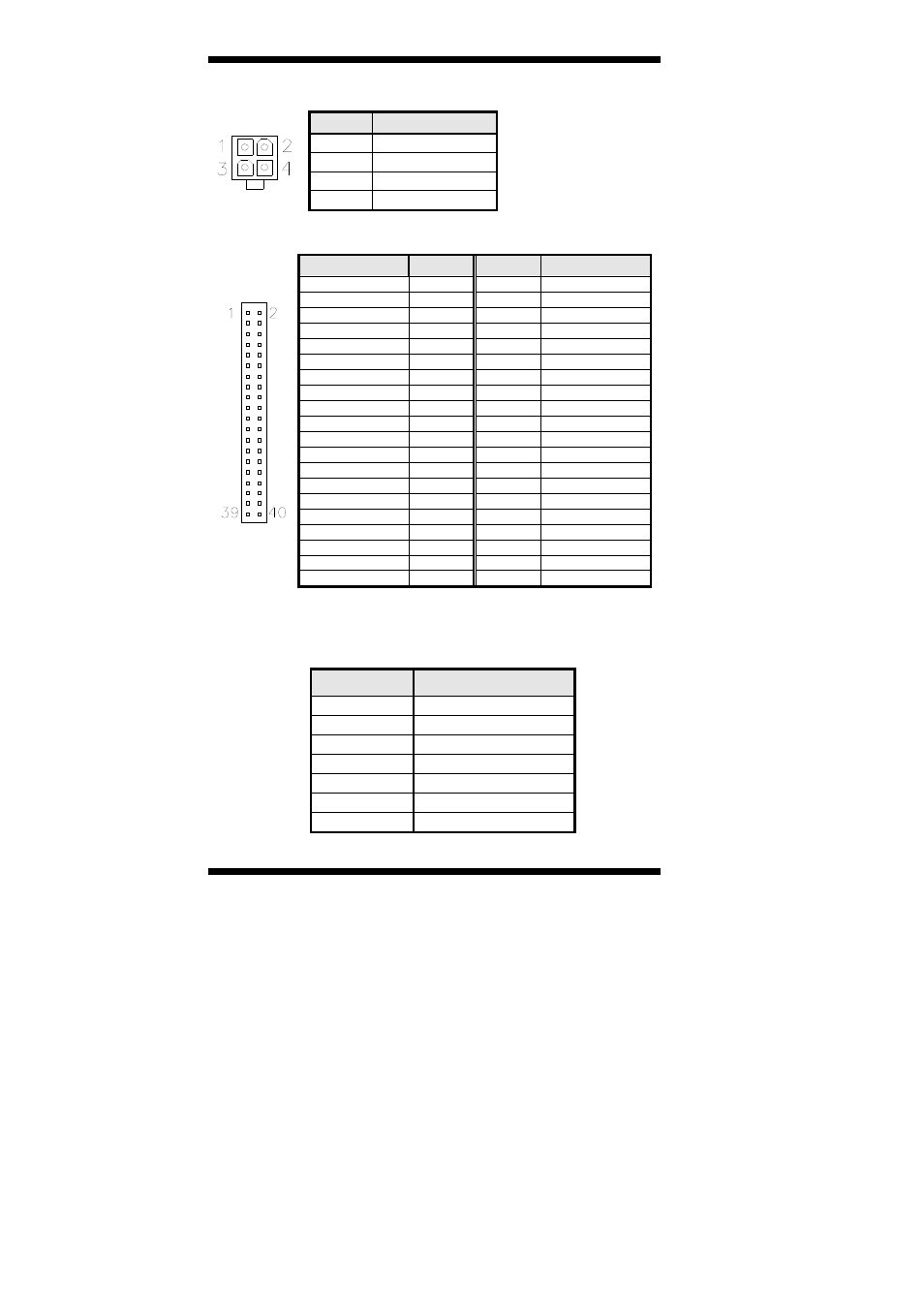
ATX1: ATX 12V/+12V Power Connector
Pin #
Signal Name
1 Ground
2 Ground
3 +12V
4 +12V
IDE1: Primary IDE Connectors
IDE1
Signal Name
Pin #
Pin #
Signal Name
Reset IDE
1
2
Ground
Host data 7
3
4
Host data 8
Host data 6
5
6
Host data 9
Host data 5
7
8
Host data 10
Host data 4
9
10
Host data 11
Host data 3
11
12
Host data 12
Host data 2
13
14
Host data 13
Host data 1
15
16
Host data 14
Host data 0
17
18
Host data 15
Ground 19
20
Protect
pin
DRQ0 21
22
Ground
Host IOW
23
24
Ground
Host IOR
25
26
Ground
IOCHRDY
27
28
Host ALE
DACK0 29
30
Ground
IRQ14 31
32
No connect
Address 1
33
34
No connect
Address 0
35
36
Address 2
Chip select 0
37
38
Chip select 1
Activity 39
40
Ground
Note: The CompactFlash interface cannot be used simultaneously
with the IDE interface.
SATA1~SATA6: SATAII Connectors
Pin #
Signal Name
1 Ground
2 TX+
3 TX-
4 Ground
5 RX-
6 RX+
7 Ground