IBASE IB945 User Manual
Page 19
Advertising
INSTALLATIONS
IB945 User’s Manual
15
J5: PCI WOL Connector
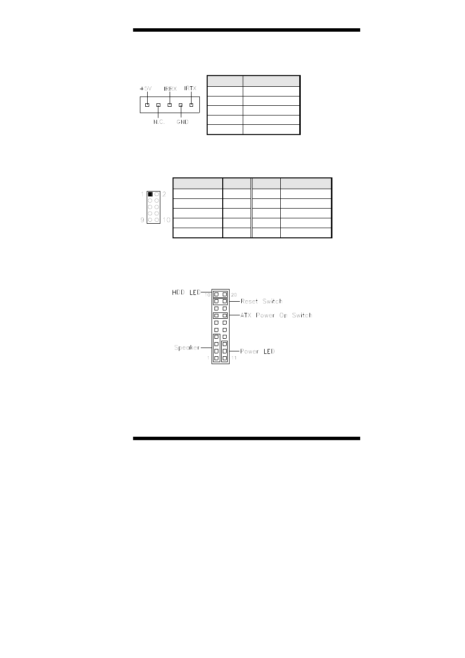
J7: IrDA Connector
Pin #
Signal Name
1 +5V
2 No
connect
3 Ir
RX
4 Ground
5 Ir
TX
J8: Digital I/O Connector (4 in, 4 out)
This 10-pin digital I/O connector supports TTL levels and is used to
control external devices requiring ON/OFF circuitry.
Signal Name
Pin #
Pin #
Signal Name
Ground 1 2 +5V
Out3 3
4 Out1
Out2 5
6 Out0
IN3 7
8 IN1
IN2 9
10 IN0
J9: System Function Connector
J9 provides connectors for system indicators that provide light indication
of the computer activities and switches to change the computer status.
Advertising