James Loudspeaker 101SA-6 User Manual
101sa-6
101SA-6
1
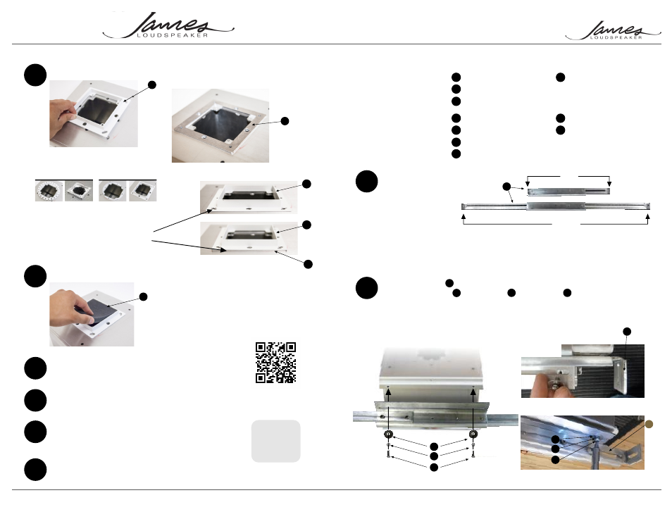
Assemble the parts
11”
22.5”
The brackets (Part No.
SA-BRKT-11-22) are
designed for 16” On-
center constructions,
however can be adjusted
to accomodate
construction from 11” to
22.5” joist spacing
(Fig. 1).
2
Attach the brackets to the speaker using the
supplied 8/32 screws , lock washers & flat washers .
Tighten these screws just enough to allow movement for
adjustment during installation.
Note: brackets can be mounted
to either the sides or the ends of the speaker for added
installation flexibility.
Tools Required:
1) #2 Phillips screwdriver
or drill with #2 Phillips
drill bit
2) Straight edge or level
3) Wood or drywall screws
4) Allen key (optional)
1 - 101SA-6 or 101SAS-6
2 - Mounting Brackets
4 - 8-32 x 1/2 Pan Head
Machine Screws
4 - #8 Lock Washers
4 - #8 Flat Washers
4 - 6/32 Course Head Screws
1 - Foam Dust Guard
A
B
C
D
E
1 -Trim Ring
Spacer Ring(s)
H
I
J
B
E
D
Parts List: Supplied
Parts: Supplied by Installer
4 - 1.25” Wood or drywall
screws
Parts: Ordered Separately
F
G
C
E
D
C
Fig. 3
Fig. 1
C
Installation guide for the 101SA-6 In-Ceiling Speaker.
B
B
D
E
11
Install foam dust guard
13
Drywall, tape, mud, etc.
Use optional spacer to adjust height
P/N SA101-SP-0.125
10
Attach the finishing trim kit
There are four trim kits
available to choose from
14
Safely store the supplied grille for the final
assembly. If you also received the 101SAM-6
module, store this as well.
Fig. 17
Fig.t 16
Fig. 20
G
J
I
For omit spacer (a)
1/2” Drywall
For use spacer (b)
5/8” Drywall
If the drywall is in excess of 5/8”
add additional 1/8” spacers
as needed.
Fig. 18
Fig. 19
I
I
J
15
If you received a 101SAS-6
preconstruction assembly, be sure to order
the 101SAM-6 module when ready for
finishing.
535 Airpark Road, Napa, CA 94558 | Ph: 707.265.6343 Fx: 707.265.6334 | www.jamesloudspeaker.com
SA101-5R-SR SA101-4S-SR
SA101-5R-W
SA101-4S-W
For Solid Surfaces
For Sheet Rock
Page 1
Page 4
B
Fig. 2
I
Products suitable for use in
outdoor dry environments
63SA-7
Installation
Video
FREQ. RESPONSE
IMPEDANCE
SENSITIVITY
AMP RANGE
RMS POWER
33-150Hz +/-3dB
8 Ohms
87dB @ 2.83V/1M
100-350 Watts
88 Watts
Fig. 4
Fig. 15
BACK
ORDER
101SA-6-INSTALL 140621
12
Recommend testing sub to assure all components
are working.