Kemppi Kempomat 1701 User Manual
Page 7
© KEMPPI OY
KEMPOMAT 1701, KEMPOMAT 2100 / 0531 – 7
3.2. Main switch
In position I control circuit of the unit is live and indicator light of main switch is on. Power
source and welding circuit become active, when gun trigger is pressed.
Note. If mains power is shut off or triggered, you must wait 10 to 15 sec, before switching
power back on.
Always switch the unit on and off from the main switch. Do not use the mains plug as a
switch!
Beware that neither you yourself, gas bottles nor electric equipment become a
part of the welding electric circuit!
3.3. To select polarity for welding
Solid wire is usually welded in + pole and cored wire in - pole gun. Check for the recom-
mended polarity on package or product seller. When welding very thin plates (0.5 to 0.7 mm)
- polarity might also work best for solid wire.
3.4. Adjustment for arc roughness I II
Arc roughness is set by connecting the return current cable or polarity selector cable to the one
of the two dix connectors on the front plate.
The connector marked with symbol I gives a rougher arc, which is used for welding of thin
sheets and ferrous metals by lower currents. Consider especially with CO
2
shielding gas.
The connector marked with symbol II is suitable for greater currents and especially for alumin-
ium and stainless materials. The most suitable roughness is, however, most dependent on the
welding case. You will find the best position by testing.
3.5. Earthing
If possible, always fix the earth clamp of return current cable directly on the welding target.
Clean earth clamp touch surface of paint and rust. Secure clamp so, that the surface it is touch-
ing is as large as possible. Finally check that clamp sits tightly.
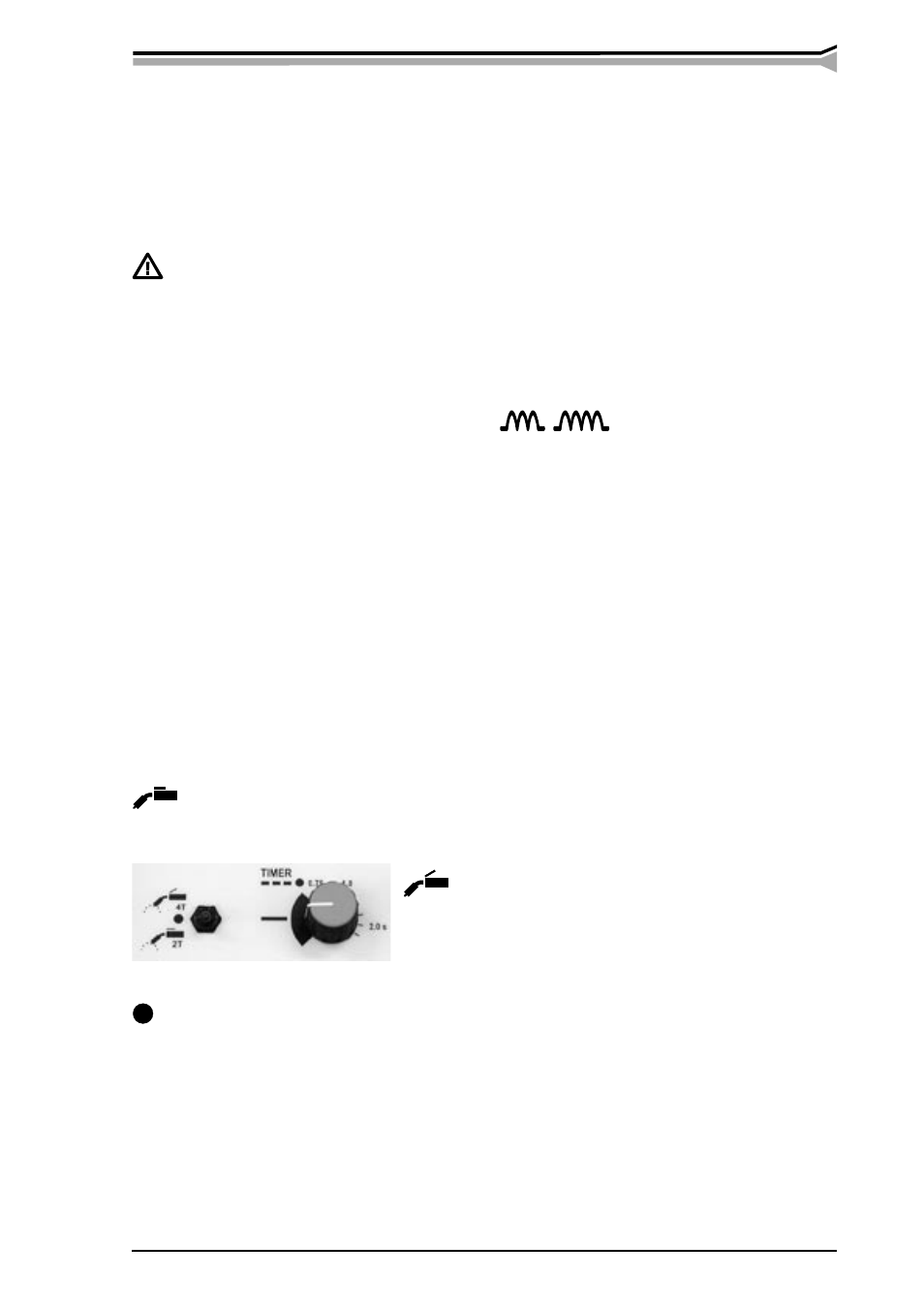
3.6. To select welding mode
Also see section 1.4. Switches and controls.
Use the welding mode selecting switch to select how to regulate shield gas flow and wire feed
in welding gun switch. You have three welding modes to select from:
2T –sequence procedure
Gas flow and wire inch start when gun switch is pressed and end when the switch is released.
Wire feed is in cycles, if timer potentiometer is set on time scale range.
4 T -sequence procedure
Gas flow starts when gun switch is pressed all the way.
When the switch is released, wire inch starts and welding
begins. When the gun switch is pressed again, wire inch is
interrupted and when the switch is released, shield gas flow
ends. Wire inch will be in cycles, if timer potentiometer is set on time scale range.
Spot welding procedure
Shield gas flow and wire inch start, when gun switch is pressed all the way and end when time
set by the timer potentiometer ends or when the gun switch is released. If the timer potentiometer
is in 0 range this procedure will not start.
TIMER potentiometer
Welding can be spaced by selecting a time for welding period on timer potentiometer. Wire feed
and gas flow will be automatically interrupted after set time and automatically restarted.
/Kempomat 2100