5 general view of the machine – Kemppi LT 250 User Manual
Page 7
Advertising
EN
2.5
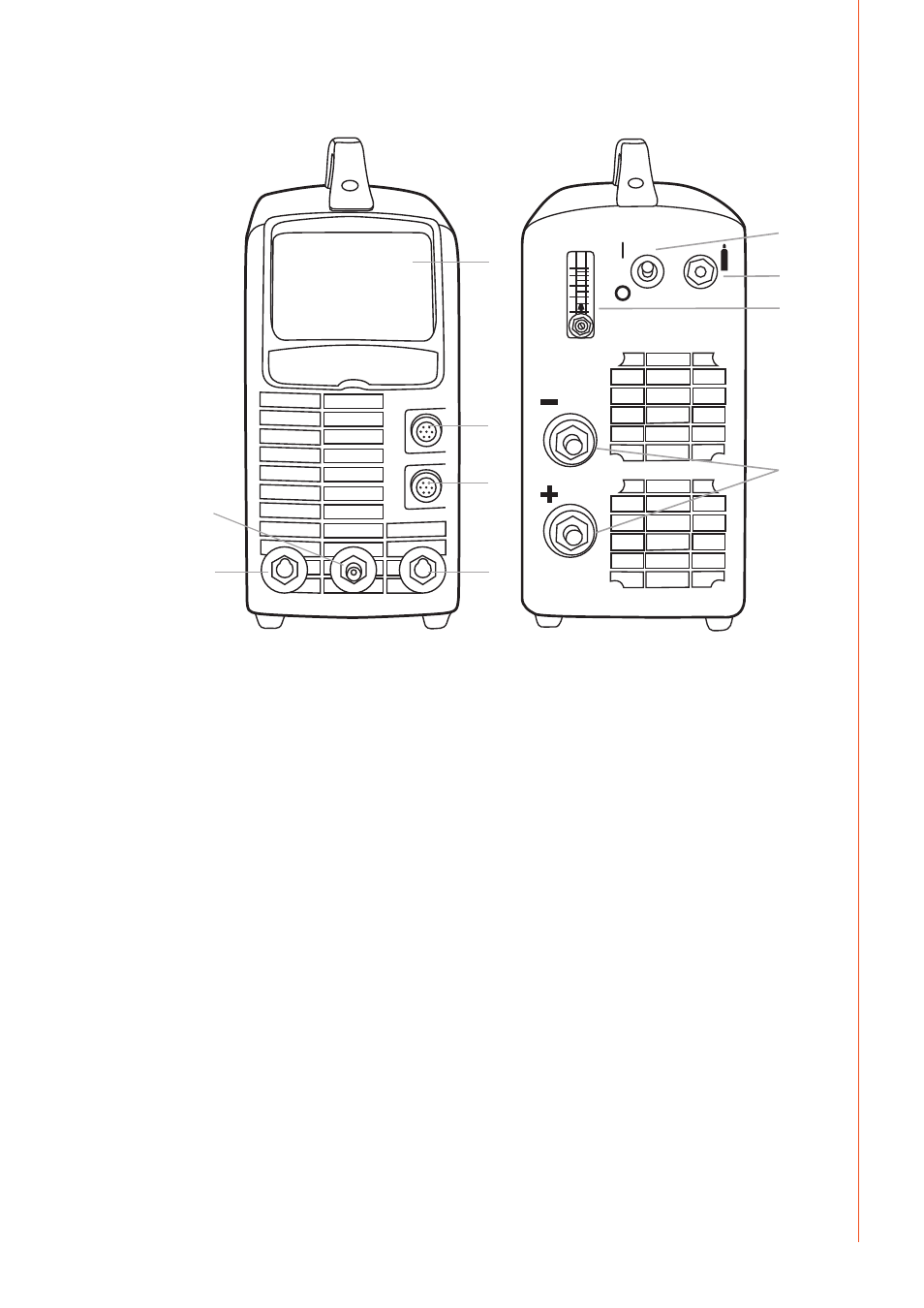
General view of the machine
7.
10.
9.
8.
1.
2.
3.
5.
6.
4.
Front of machine
1. Control panel
2. Remote control connector
3. TIG torch control connector
4. Shield gas and current connector for TIG torch
5. (+) connector for electrode holder
6. (–) connector for earth cable
Markings for (+/–) poles on the machine front are embossed.
Rear of machine
7. ON/OFF switch
8. Snap connector for gas
9. Shielding gas flow meter
10. Welding cables connectors from parent source
NOTE!
MasterTig LT 250 is polarity protected. If the +/- power cables are connected in reverse the
machine will not function. This is evident by no power to the control panel.
5
© Kemppi Oy / 1422
Advertising