2 ptc and olp, 3 defrost timer – Kleenmaid TBR351ANBRWH User Manual
Page 11
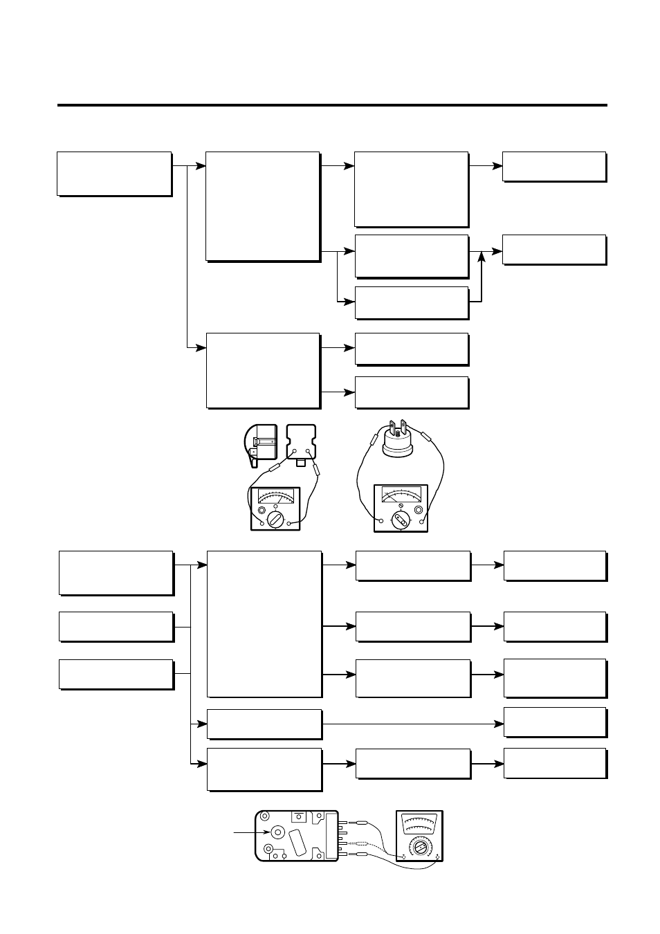
6-2 PTC AND OLP
- 11 -
6-
5-
YES-
NO-
NO-
YES-
NO-
Cam Shaft-
Normal operation of
Compressor is
impossible or poor.
Separate the PTC-
Starter from
Compressor and
measure the
resistance between
No. 5 and 6 of PTC-
Starter with a Tester or
Whistone Bridge.
(Figure 21)
Separate the OLP from
Compressor and check
the resistance value
between two terminals
of OLP with a Tester.
(Figure 22)
Observation value is
220V/50Hz : 22
§
±30%
115V/60Hz : 6.8
§
±30%
240V/50Hz : 33
§
±30%
127, 220V/60Hz : 22
§
±30%
The resistance value
is 0 or several
hundreds
§
.
The value is
¡˜
.
Check another
electric components.
Replace OLP.
Check another
electric components.
Replace PTC-
Starter
Figure 21
Figure 22
Figure 23
Normal operation of
the Defrost Timer is
impossible.
No defrosting.
Poor cooling.
Position the Cam Shaft to
the point of first 'click'
sound and check the
current flowing between
terminals No. 1(brown)
and No. 2(bright orange).
Next, position the Cam
Shaft to the point of
second "click" sound and
check the current flowing
between terminals
No. 1(brown) and
No. 4(black)
(Figure 23).
Turn the Cam Shaft.
Shake about 3 times
with holding the Cam
Shaft and Body softly.
The resistance is
¡˜
The resistance is
0
§
or variable.
The resistance is about
220V/50Hz : 20K
§
115V/60Hz : 7.8K
§ .
Loud 'click' sound.
Replace the
Defrost Timer.
Replace the
Defrost Timer.
Replace the
Defrost Timer.
Check the another
electric components.
Replace the
Defrost Timer.
6-3 DEFROST TIMER