Convia enable walkerflex system installation, Network hubs – Legrand Convia Enabled Walkerflex System User Manual
Page 3
3
CONVIA ENABLE WALKERFLEX SYSTEM INSTALLATION
(continued)
Network Hubs
The Network Hub module makes up the
backbone or Main Bus of the network. Multiple
Network Hubs can be configured to increase the
size of the network or to increase the number of
available ports in an installation location. Up to 50
Network Hubs can be connected on a single
network with a patch cable length of up to 2000
feet. Refer to the ConviaNet Design Guide for
more information.
Mounting Holes
120V SYSTEM
Part
Walkerflex
Number
Phase
Configurations
NVHUBA
A
111, 211, 311
NVHUBB
B
211, 311
NVHUBC
C
311
NVHUBD
222
NVHUBF
Field Wired
277V SYSTEM
Part
Walkerflex
Number
Phase
Configurations
LVHUBA
A
111, 211, 311
LVHUBB
B
211, 311
LVHUBC
C
311
LVHUBF
Field Wired
LVHUBF
Field Wired
Table A – NETWORK HUB POWER CONFIGURATIONS
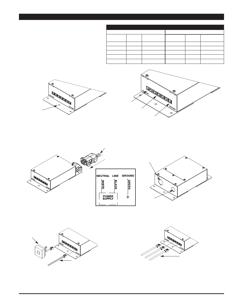
Step 1:
Mount Network Hub securely using
appropriate screws and anchors.
RJ11 Jack for Main
Bus Connections
RJ45 Jacks for Node
Bus Connections
RJ11 Jack for Main
Bus Connections
Step 2:
Connect Power to Network Hub.
For Modular Connection: Connect Convia
Enable Walkerflex Modular Cable
to modular input.
For Field Wired Units: Connect conduit to appropriate
conduit opening and wire per the National Electric
Code. (See Wiring Schematic below or on product
label for connections.
Hub Wiring Schematic
Prewired 5-Port Network Hub
Field Wired 5-Port Network Hub
Power input coming
from Distribution Box
or main panel
Current Flow
Direction
3/4" Trade Size
Knockout
1/2" Trade Size
Knockout
Step 3:
Connect Wiremold Convia Enabled pre-terminated
RJ11 cables between the Network Hubs. Install
Communication Loop Closures into RJ11 ports at the
beginning and end of the network run (Main Bus).
Step 4:
Install Wiremold Convia Enabled pre-terminated
RJ45 cables between the Network Hubs and the
Relay Dimmers, Power Modules, Sims, Switches,
and Scene Controllers.
Wiremold Convia
Enabled Pre-terminated
RJ11 Cable to next
Network Hub in network
Communications Loop
Closure – 2 required
for each network
NOTE: To ensure proper network functioning, Communication
Loop Closures need to be installed into the beginning
and end of the Main Bus of the network. If there is
only one Network Hub in the installation, then
Communication Loop Closures must be installed in
both RJ11 ports on the Network Hub.
Wiremold Convia Enabled Pre-
terminated RJ45 Cables going
to Relay Dimmers, Power
Modules, Sims, Switches and
Scene Controllers
Step 5:
Move on to the installation of Relay Dimmers
and Power Modules.