Convia enable walkerflex system installation, Power modules – Legrand Convia Enabled Walkerflex System User Manual
Page 6
6
CONVIA ENABLE WALKERFLEX SYSTEM INSTALLATION
(continued)
Power Modules
The Power Modules are used to control
general purpose loads, (maximum 20A load)
via the Convia Enabled Walkerflex System.
They connect to the Network Hub to create
the Node Bus of the network. Up to 25
nodes can be connected on a single Node
Bus with a maximum patch cable length of
1000 feet. Refer to the ConviaNet Design
Guide for more information.
Part
Number of
Number of
Walkerflex
Walkerflex
Number
Controlled Circuits
Total Circuits
Input(s)
Output(s)
NPM12
1
2
222
222
NPM22
2
2
222
222
NPM12F
1
2
Field Wired
NPM22F
2
2
Field Wired
NPM24
2
4
422
(2) 222
NPM44
4
4
422
(2) 222
NPM24F
2
4
Field Wired
NPM44F
4
4
Field Wired
NPM24PF
2
4
422
422
NPM44PF
4
4
422
422
Table C – POWER MODULE CONFIGURATIONS
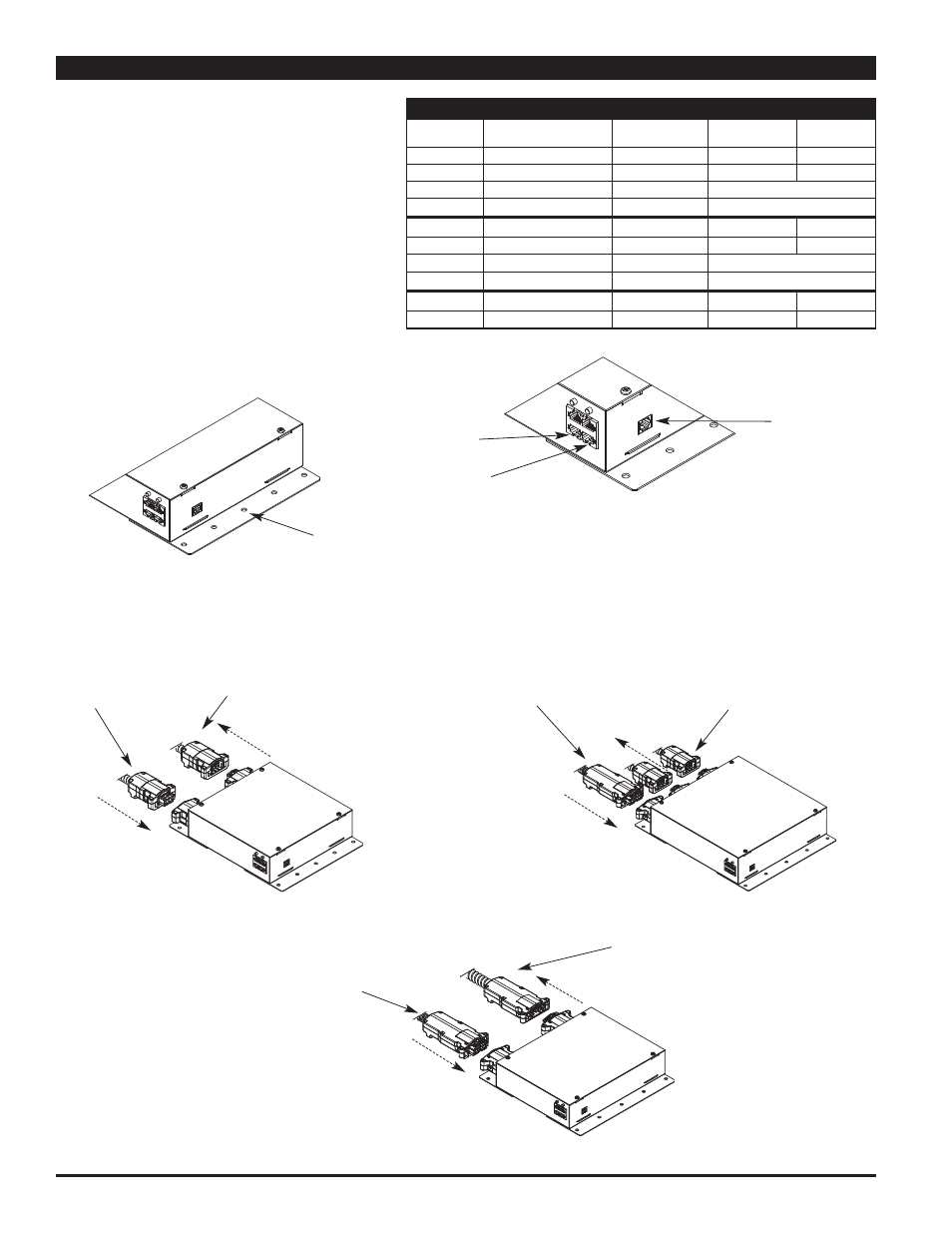
Step 1:
Mount Power Modules securely using
appropriate screws and anchors.
Mounting Holes
ConviaNet
(RJ45) Jack for
Accessory Bus
Connections
ConviaNet (RJ45)
Jack for Node
Bus Connections
ConviaIR (RJ11)
Jack for IR
Connections
Step 2:
Connect Power to Power Modules.
For Modular Connection: Connect Convia Enabled Walkerflex Modular
Cable to modular input and output(s).
Power input coming
from Distribution Box
or main panel
Current Flow
Direction
Power Output going to
Floor Boxes, Poke-Thru
Devices, etc.
Current Flow
Direction
Two Circuit Power Modules
Four Circuit Power Modules
Power input coming
from Distribution Box
or main panel
Current Flow
Direction
Power Output going to
Floor Boxes, Poke-Thru
Devices, etc.
Current Flow
Direction
Power input coming
from Distribution Box
or main panel
Current Flow
Direction
Power Output going to
Floor Boxes, Poke-Thru
Devices, etc.
Current Flow
Direction
Four Circuit Partition Feed Modules