Legrand Convia Enabled Walkerflex System User Manual
Page 7
7
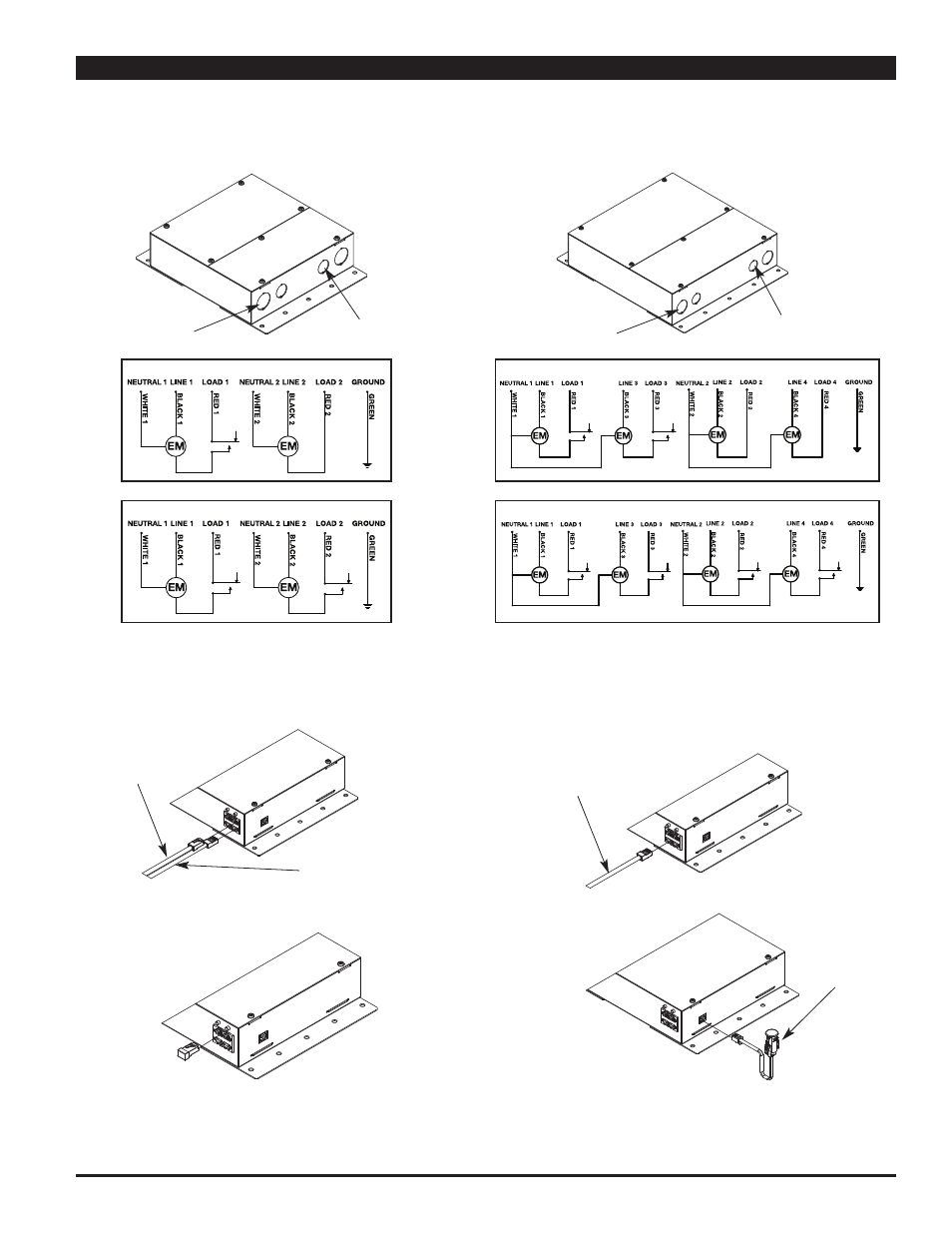
For Field Wired Units: Connect conduit to appropriate conduit opening and wire per the National
Electric Code. (See Wiring Schematic below or on product label for connections).
3/4" Trade Size
Knockout
1/2" Trade Size
Knockout
Two Circuit Power Modules – Field Wired
Four Circuit Power Modules – Field Wired
CONVIA ENABLE WALKERFLEX SYSTEM INSTALLATION
(continued)
Step 2 (continued):
1/2" Trade Size
Knockout
3/4" Trade Size
Knockout
NPM12 Wiring Schematic
NPM24 Wiring Schematic
NPM22 Wiring Schematic
NPM44 Wiring Schematic
Step 3:
Connect Wiremold Convia Enabled pre-terminated
RJ45 cables between the Network Hubs and the
Power Modules to create the Node Bus. The top
ConviaNet RJ45 jack is IN, the bottom ConviaNet
RJ45 jack is OUT.
Step 4:
Connect Wiremold Convia Enabled pre-terminated
RJ45 cables between the Power Modules and the
Sims, Switches, and Scene Controllers to create
the Accessory Bus. An Accessory Bus can contain
up to 50 devices with a maximum patch cable
length of 500 feet.
In from Network
Hub or upstream
Relay Dimmer or
Power Module
Out to downstream
Relay Dimmer or
Power Module
Out to Sim, Switch
or Scene Controller
Step 5:
Install End Terminators in all ConviaNet RJ45
Node Bus terminals not being used.
Step 6:
Install IR Sensors into ConviaIR RJ11 Port.
IR Sensor
NOTE: To ensure proper network functioning, End Terminators
need to be installed in all unused Node ports, and End
Terminators or Inline Terminators need to be installed
at the end of all Accessory Bus Runs.
NOTE: IR Sensor can be installed using a RJ11 In-Line
Connector (PNRJ11LC) and a Wiremold Convia Enabled
pre-terminated RJ11 Cable when necessary. IR Sensors
are needed in all boxes for commissioning and are
recommended to aid in reconfiguring or troubleshooting
network setups.