Table 1 table 2 – Legrand Wallduct Medical Raceway System Bodies User Manual
Page 10
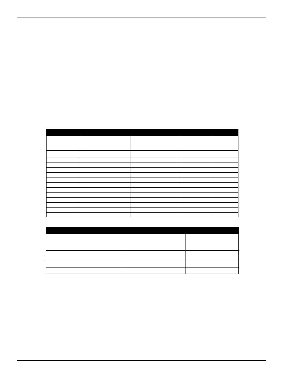
Deduct for
Deduct for
DEDUCT FOR
DEDUCT FOR
MATERIAL THICKNESS
MATERIAL THICKNESS
MAXIMUM RACEWAY
(LEFT & RIGHT)
(BOTTOM)
WIDTH (In.)
Inches
[mm]
Inches
[mm]
6" – 18" [15.2 – 45.7cm] Steel
0.156"
[3.962]
0.078"
[1.981]
20" – 30" [50.8 – 76.2cm] Steel
0.216"
[5.486]
0.108"
[2.7432]
6" – 18" [15.2 – 45.7cm] Aluminum
0.200"
[5.080]
0.100"
[2.540]
20" – 30" [50.8 – 76.2cm] Aluminum
0.250"
[6.35]
0.125"
[3.175]
WIREFILL AND IMPORTANT UL INFORMATION
Use these steps to determine Wirefill Capacity
Step 1: Determine the internal raceway area by multiplying the overall width by the overall depth (subtract
material thickness).
Example: Assume you have a steel raceway 10" wide by 4" deep [254mm wide by 101.6mm deep].
Subtract the material thickness from each dimension (see Table 2). This results in an internal
raceway dimensions of 9.844" [250mm] (10" – 0.156" [ 254mm – 3.96mm]) wide by 3.922" [100mm]
(4” – 0.078" [101.6 – 1.98mm]). The internal area for this raceway size would be 38.6 sq.in.
[249.03cm
2
] (9.844" x 3.922").
Step 2: Determine the number of conductors allowed inside the raceway for a given type and size (types THHN
and THWN are shown in Table 1) of conductor by multiplying the internal area (calculated in Step 1) by
the number of conductors allowed per square inch (see Table 1).
Example: Assume you want to calculate how many No. 6 AWG (THHN) conductors you are allowed
to place in the 10" by 4" [254mm x102mm] raceway in step 1 at 40% wire fill capacity. Multiply the
internal area of the raceway by the maximum number of wires allowed per square inch, from Table 1.
This results in 304 allowable cables (38.6 sq. in. x 7.89 [249.03cm
2
x 7.89]).
THHN/THWN
APPROXIMATE
APPROXIMATE
20% FILL
40% FILL
WIRE SIZE
OUTSIDE DIAMETER
AREA
(Per In.
2
)
(Per In.
2
)
GAUGE NO.
In.
[cm]
In.
2
[cm
2
]
[6.45cm
2
]
[6.45cm
2
]
14
0.111
[.2819]
0.0097
[.0625]
20.62
41.24
12
0.130
[.3302]
0.0133
[.0851]
15.04
30.08
10
0.164
[.4166]
0.0211
[.1361]
9.48
18.96
8
0.216
[.5486]
0.0366
[.2361]
5.46
10.93
6
0.254
[.6452]
0.0507
[.3271]
3.94
7.89
4
0.324
[.8230]
0.0824
[.5316]
2.43
4.85
3
0.352
[.8941]
0.0973
[.6278]
2.06
4.11
2
0.384
[.9754]
0.1158
[.7471]
1.73
3.45
1
0.446
[1.1328]
0.1562
[1.0077]
1.28
2.56
1/0
0.486
[1.2344]
0.1855
[1.1968]
1.08
2.16
2/0
0.532
[1.3513]
0.2223
[1.4343]
0.90
1.80
3/0
0.584
[1.4834]
0.2679
[1.7285]
0.75
1.49
4/0
0.642
[1.6307]
0.3237
[2.0885]
0.62
1.24
TABLE 1
TABLE 2
A 20% fill should be used for systems utilizing fittings that have sharp 90º turns. The derating factors of NEC
article 310.15(B)(2)(a) shall apply to conductors installed if the amount of current-carrying conductors exceeds
30 in number, or the sum of the cross-sectional area of all conductors exceeds 20 percent of the interior
cross sectional area of the raceway. When tunnels are utilized, the internal cross sectional area must be
further reduced by 50 percent. When partitions are utilized, the internal cross sectional area must be calculated
for each individual compartment.