Display, Rear panel – Marantz SA-14S1N User Manual
Page 12
5
ENGLISH
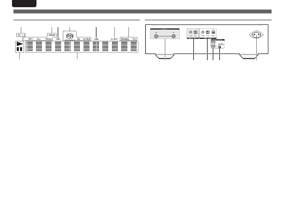
Display
q
Play mode indicator
3 : This indicator lights up during pause.
1 : This indicator lights up during playback.
w
Main display area
This area displays the time display and text
information of the disc to be played, as
well as the setting menu items, etc.
e
Time mode indicator
REMAIN : This indicator lights up while
the remaining track time is
displayed.
TTL : This indicator lights up while the total
remaining time.
r
Digital output off indicator (D OFF)
This indicator lights up when the digital
output setting is set to off (vpage 16).
t
USB indicator
This indicator lights up during operation in
the USB mode.
y
Disc indicator
This indicator displays the disc type which
is currently in the disc tray.
“M FILE” lights up if the disc contains
WMA/MP3 files.
u
TRK indicator
This indicator lights up above the display
of the track number currently being played.
i
Special play mode indicator
1 : This indicator lights up during repeat
play of one track.
RPT : This indicator lights up during repeat
play.
ALL : This indicator lights up during repeat
play of all tracks.
RNDM : This indicator lights up during
random play.
PROG : This indicator lights up during
program play.
o
Filter indicator (FIL 1 2)
This indicator shows which filter (Filter 1 or
Filter 2) is selected (vpage 23).
y
o
i u
t
r
e
w
q
Part names and functions
Rear panel
q
AUDIO OUT connectors
Used to connect to an amplifier
(vpage 8).
w
DIGITAL AUDIO OUT connectors
(COAXIAL/OPTICAL)
Used to connect to a device with digital
audio input connectors (vpage 9).
e
DIGITAL AUDIO IN connectors
(COAXIAL/OPTICAL/USB-DAC)
Used to connect to a device with
digital audio output connectors or a PC
(vpage 9).
r
REMOTE CONTROL IN / OUT
connectors
Used to connect to a Marantz amplifier
that is compatible with the remote control
function (vpage 11).
r t
y
q
w
e
t
EXTERNAL/INTERNAL switch
Turn this switch to “EXTERNAL” to
operate the unit by pointing the remote
control at the amplifier connected to this
unit using the remote control connection
(vpage 11).
y
AC inlet (AC IN)
Used to connect the power cord
(vpage 12).