Caution, Service – Maytag MEW5530BCW Installation User Manual
Page 2
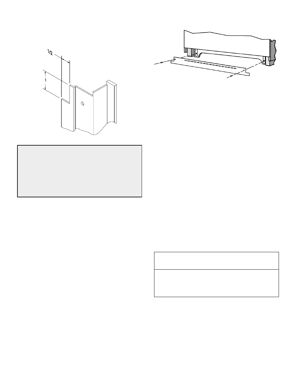
When installing a 27
²
wall oven under a 30
²
cooktop
some interference may occur. The following cutout
notching of the side trims will eliminate the interference of
the side trim to the burner box. After cutting, file the side
trim edges to eliminate burrs.
CAUTION
For European style cabinets (flush front) the required
clearance for operation of the oven door is minimum
spacing of 7/8
²
between the cutout and the door, hinge
or drawer of the cabinet.
Some built-in cabinets may not be wide enough, due to
their construction, to allow this installation.
1. Cut hole in cabinet to mount oven. Cutout in cabinet
should be level and straight.
NOTE:
There are no provisions to level the unit after it
is installed. An oven that is not level could cause poor
baking results.
2. Install plywood floor as shown.
3. Attach unit to the cabinet with four No. 8 x 1
²
screws
supplied with unit inside of envelope containing these
instructions. Pre-drill holes in cabinet for attachment
screws using 1/8
²
drill. Oven mounting holes are
provided in side trim.
4. See instructions at right for electrical hook-up.
5. See Use and Care Manual for operating instructions.
Installing Bottom Trim Piece
Electrical Connections
Unit to be properly circuit protected and wired according
to local electrical code and National Electrical Code.
It is advisable that the electrical wiring and hookup be
accomplished by a competent electrician.
120/240 VAC or 120/208 VAC 60 Hz. See serial plate on
front of unit for power requirements.
The neutral of this unit is grounded to the frame through
the green or solid grounding wire. (The green and the
white wires are twisted together at the termination of the
conduit.) If used on new branch-circuit installations (1996
NEC), mobile homes, recreational vehicles, or in an area
where local codes prohibit grounding through the neutral
conductor, untwist or disconnect the green wire and
connect the green wire to ground in accordance with local
code. Connect the white neutral to the service neutral.
Connect all wires to the branch circuit with approved
connectors. Use copper or aluminum wire. If aluminum
wire is used, use connectors recognized for joining
aluminum to copper.
The chart below recommends the minimum circuit
protection and wire size if the appliance is the only unit on
the circuit.
K.W. RATING
ON SERIAL PLATE
0 -- 4.8
4.9 -- 6.9
7.0 -- 9.9
10.0 -- 11.9
12.0 -- 14.9
RECOMMENDED MINIMUM
CIRCUIT PROTECTION
IN AMPERS
20
30
40
50
60
WIRE SIZE
(AWG)
12
10
8
8
6
Service
Interrupt the source of electricity to the unit when
attempting to repair or service the oven. Failure to do this
could result in a dangerous or even fatal shock.
IMPORTANT - SAVE FOR LOCAL ELECTRICAL INSPECTOR’S USE