3 analog output range jumper – Measurement Computing PC104-DAC06 User Manual
Page 8
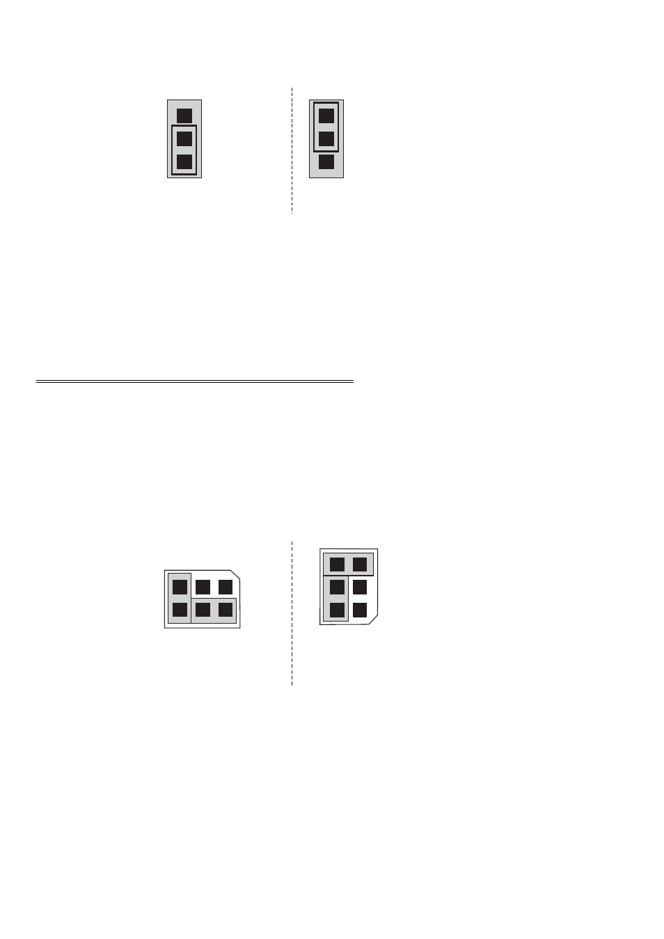
Figure 3-2 shows the jumper block in each configuration. Place the jumper on the two
pins closest to the word XFER for simultaneous transfer.
Figure 3-2. Simultaneous Transfer Jumpers
Jumper #
DAC Controlled
J1
DAC 0 & 1
J2
DAC 2 & 3
J3
DAC 4 & 5
3.3 ANALOG OUTPUT RANGE JUMPER
The analog output voltage range of each channel can be set via a six pin jumper block.
The switches are located on the board near the DACs they control and are labeled S1
through S6. The number corresponds to the DAC under control + 1.
Set the jumpers for an individual channel using Figure 3-3 to orient the jumper block
pin 1, and Table 3-2 below to select the range.
Figure 3-3. Range Jumpers
4
XFR
XFR
Shown for individual
transfers per channel.
Shown for simultaneous transfer
of both channels.
SIMULTANEOUS TRANSFER JUMPERS - One per pair of channels.
Position of S# relative
to pin1 for S1-S4
Position of S# relative
to pin 1 for S5 & S6
JUMPERS SHOWN +/-5v RANGE
5
3
1
S#
6
4
2
6
4
2
5
3
1
S#