Page 9 – MicroE 3500Si Mercury User Manual
Page 11
Page 9
Reference Section
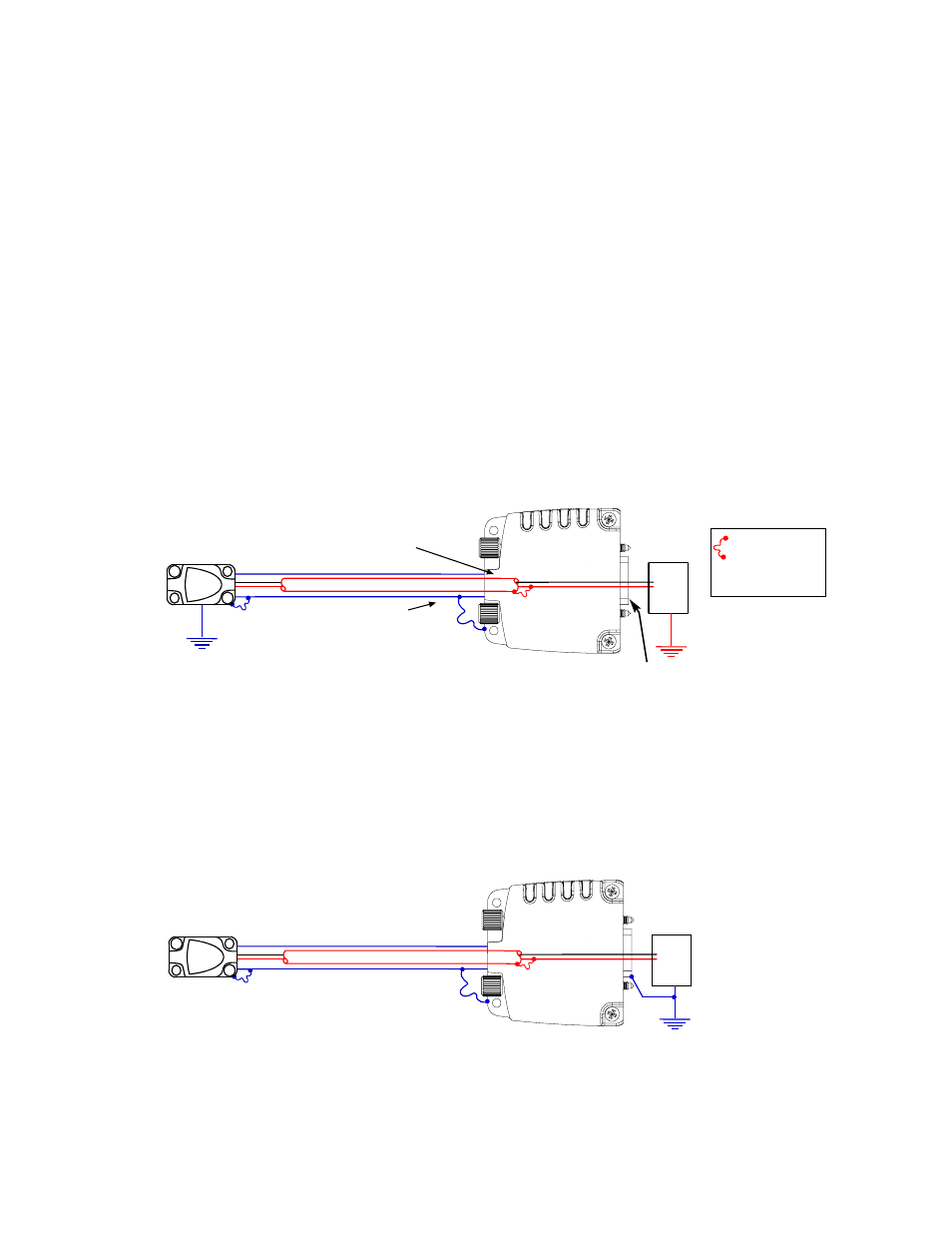
Sensor mounted with good electrical contact to a well-grounded surface (preferred)
1. 15-pin D-sub connector grounding: The encoder's connector shell must be in intimate, electrically conductive contact with the customer-
supplied mating connector, which must be isolated from the controller's ground. If a customer-supplied shielded cable connects the encoder
to the controller, then the shielding on the customer-supplied cable must be isolated from the controller's ground.
2. The sensor mounting surface must have a low impedance (DC/AC) connection to ground. The encoder sensor mounting surface may have to
be masked during painting or anodizing to insure good electrical contact with the sensor.
For Mercury 2000 and 3000 encoder systems to operate reliably, it is essential that the sensor and cable shield are grounded properly
according to the following instructions. The diagrams below show how to make the connections when the encoder's connector is
plugged into the customer's controller chassis. If a customer-supplied extension cable is used, it should be a double shielded cable with
conductive connector shells and must provide complete shielding over the conductors contained within it over its entire length.
Furthermore, the shields should be grounded at the connection to the controller chassis the same way as the encoder connectors in the
diagrams below.
Note: For best performance, isolate encoder shield from motor cable shields and separate encoder cable as far possible from motor cables.
Sensor mounted to a surface that is grounded through bearings or a poorly-grounded surface, or a non-conducting surface
1. 15-pin D-sub connector grounding: The encoder's connector shell must be in intimate, electrically conductive contact with the customer-supplied mating
connector, which must be connected to the controller's ground. If a customer-supplied shielded cable connects the encoder to the controller, then the
shielding on the customer-supplied cable must be connected to the controller's ground. The controller must be grounded to earth at the point of installation.
2. The encoder sensor must be mounted so that it is electrically isolated from ground.
Mercury encoders require a minimum of 4.75V DC continuously. When designing circuits and extension cables to use Mercury encoders, be sure to
account for voltage loss over distance and tolerances from the nominal supply voltage so that at least 4.75V DC is available to the Mercury encoder
under all operating conditions. The input voltage should not exceed 5.25V DC.
Outer Shield: Connected to Sensor
and Connector housing
5 Volts
0 Volts
Power
Supply
Grounding Instructions for Mercury 3500Si Encoder Systems
Recommendations for Power
Outer Shield: Connected to Sensor
and Connector housing
Inner shield: Insulated from outer shield,
sensor, and connector housing. Connected
to circuit common internally (pin 4).
5 Volts
0 Volts
Power
Supply
Electrically conductive
mechanical connection
(as supplied by MicroE
Systems).
Do not ground shroud.