Rotary encoder alignment, Installation instructions, Iim mp po or rt ta an nt t – MicroE 3500Si Mercury User Manual
Page 9: Rotary encoders - using alignment tool - alignment
Installation Instructions
Rotary Encoders - Using Alignment Tool - Alignment
Page 7
6
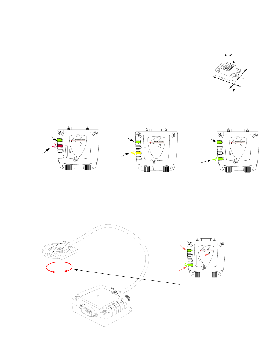
Confirm proper alignment
over the full range of motion.
The “Proper Alignment” LED
must remain on over the
entire range. If not aligned
over the entire range of
motion, loosen the sensor
mounting screws and repeat
step 5.
5
If benching dimensions cannot be provided, proper sensor alignment may require minor adjustments
to the sensor position with respect to the scale. This can be performed easily using the LED alignment
indicators, as illustrated below.
The red, yellow, or green LED will light depending on sensor alignment. Slowly move the sensor by
allowing it to slide on the mounting surface until the green or Proper Alignment LED, is illuminated.
Optimal alignment will be displayed as a “Bright Green” LED.
IIM
MP
PO
OR
RT
TA
AN
NT
T:
Confirm that the Proper Alignment LED blinks when passing over the index. If not,
readjust the sensor in the Y direction and repeat the above procedure. When alignment is completed,
tighten the sensor mounting screws (0.37Nm [3.3 inch-lbs.] maximum torque).
x
Y
Z
θ
z
To align the sensor, move
it in the Y or
θ
z direc-
tions.
IIM
MP
PO
OR
RT
TA
AN
NT
T
O
OU
UT
TP
PU
UT
T C
CA
ALLIIB
BR
RA
AT
TIIO
ON
N P
PR
RO
OC
CE
ED
DU
UR
RE
E
This procedure must be completed for
proper system operation each time the
sensor is aligned or if the SmartPrecision
electronics module is replaced.
Position the sensor at
least 7mm (1/4”)
away from the index
mark on the scale.
Next, push the
Index/Calibration
button inside the
module with a small
diameter shaft, such
as a bare cotton swab.
The Power/Calibration indicator will flash contin-
uously. Move the scale past the sensor in both
directions so that the index mark passes under
the sensor. Do not run off the end of the scale
when using a segment scale. When the calibra-
tion procedure is complete, the
Power/Calibration indicator stops flashing.
7
PWR/Cal. - Signal +
Mercury 3500Si
SS-350cSi
patent
applied for
Power/
Calibration
indicator
Calibration /
Index Set
Up button
Proper
Alignment
indicator
PWR/Cal. - Signal +
Mercury 3500Si
SS-350cSi
patent
applied for
PWR/Cal. - Signal +
Mercury 3500Si
SS-350cSi
patent
applied for
PWR/Cal. - Signal +
Mercury 3500Si
SS-350cSi
patent
applied for
Improper
Alignment LED
Red
Power/
Calibration
Power/
Calibration
Power/
Calibration
Improved
Alignment LED
Yellow
Proper
Alignment LED
Green
Optimal
Alignment LED
Bright Green