Serial output specification – MicroE 3500Si Mercury User Manual
Page 16
Trigger Communication Approach:
The Trigger Approach can be used in applications where synchronization of the position data to an event is required. Often, this mode is used
when a fixed latency between a clock signal and the sampled position data is required. The customer can choose this mode of operation by using
the optional SmartPrecision Software. In this mode, triggering is controlled by the n_spiEnable signal.
The n_spiEnable signal starts the process by immediately resetting the internal calculators and acquiring the latest AD converter information. Old
data in the calculation chain is discarded and the initiation of a new position calculation is started.
The new data is ready in 1180ns. The n_spiEnable signal for retrieving the data must be asserted within 340ns after the new data is ready or the
triggered acquisition will be over written by new data.
Shifting the data out of the interpolator's serial port is accomplished exactly as in the Standard Communication mode of operation. In order to
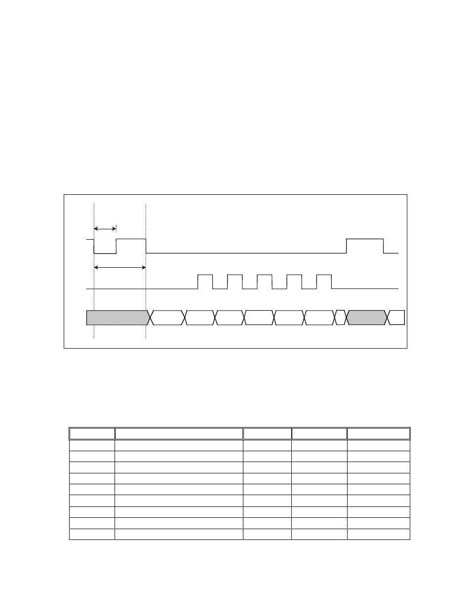
sample the next position, n_spiEnable must be brought high and then reasserted. See the Trigger Approach timing diagram below.
n_spiEnable
spiClock
spiDataOut
tTDR
tW
Symbol
Parameter
Minimum
Maximum
Units
tspiH
SCK High Time
25
ns
tspiL
SCK Low Time
25
ns
tTDR
n_spiEndable to DataReady
1180
1520
ns
tW
n_spiEnable width
50
ns
tCSD
n_spiEnable to DataValid
50
ns
tV
↓SCK to Data Valid
25
ns
tCCS
SCK to n_CS
0
ns
tCS
n_CS High
50
ns
tDNA
n_CS to HiZ (no HiZ)
50
ns
Trigger Approch Timming Diagram
Page 14