Linear encoder system diagram, Mercury 3500si encoder system, With linear scale – MicroE 3500Si Mercury User Manual
Page 4
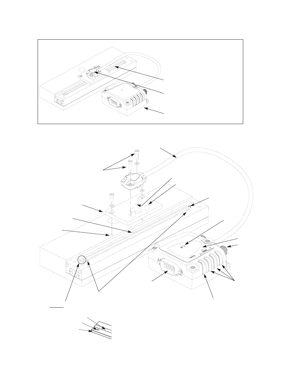
Mercury 3500Si Encoder System
with Linear scale
Page 2
E
Exxp
pa
an
nd
de
ed
d V
Viie
ew
w
Scale benching edge
End locator pin
End index mark
Sensor mounting holes (2)
Bracket mounting holes (2)
Optional sensor benching pins (3)
Double
shielded cable
Center index mark
Typical user-supplied
sensor mounting bracket
Top reflective linear scale
Detail A
15 pin High Density
D-sub connector
Thumb screw
Index /
Calibration
button
Power/Calibration Indicator
S
Syysstte
em
m V
Viie
ew
w
Shown with linear scale
Glass scale
(shown mounted on a linear slide)
Sensor
(shown attached on a linear slide base with
mounting bracket)
SmartPrecision electronics module (interpolator)
Scale reference datum;
example shown with benching pins
Cover: Sensor cable
and connector
Signal & alignment
indicators
Mounting screws & flat
washers (2 needed per screw)