Or with the teach-in procedure, Start here, Ready – Microsonic mic+25/IU/TC User Manual
Page 2
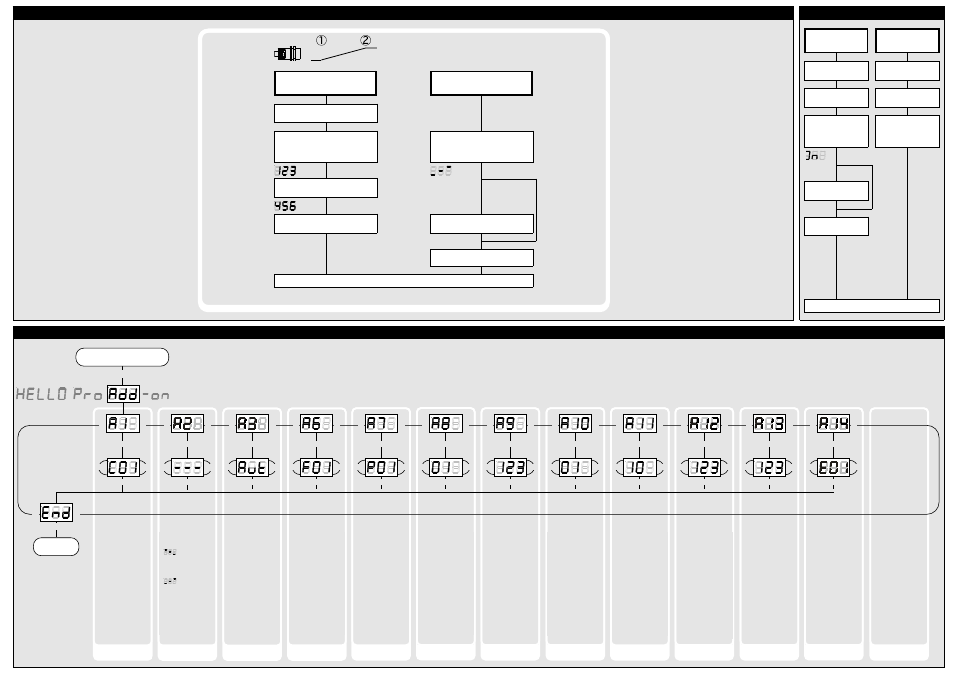
...or with the Teach-in procedure
Set window margins
Place object at position ➀
Press T1 until »IU« is shown
Place object at position ➁
Current measuring
value
Press T1 until »End« is shown
Current measuring
value
Set rising/falling output
characteristic curve
Press T1 until countdown passed
from »- 8 -« to »- 0 -« and symbol
for rising/falling characteristic
is displayed
Sybol rising/falling
characteristis
Sybol falling/rising
characteristis
To change output characteristic
press T1
Normal mode operation
Press T1 and T2 simultaneously until
»End« is displayed
T1 + T2
T1
T2
T1 + T2
Press T1 and T2 simultaneously for about 13 s
until »Add« is shown in the LED-display
T1 + T2
T2
T1
Start here
T2
T1
T1 + T2
Ready
»- - -«: Display in
mm or. cm
»
«: Display in
%, 100% at mini-
mum measured va-
lue
»
«: Display in
%, 100% at maxi-
mum measured va-
lue
»C01«: Display
bright
»C02«: Display dim-
med
»C03«: Display off
To optimize multi-
plex speed the hig-
hest sensor address
may be set.
Setting range »01«
to »10«
»F00«: no filter
»F01«: standard fil-
ter
»F02«: averaging fil-
ter
»F03«: foreground
filter
»F04«: background
filter
Defines the strength
of the chosen filter.
»P00«: weak filter
up to
»P09«: strong filter
Affects the size of
the detection zone.
»E01«: high
»E02«: standard
»E03«: slight
Minimum value:
blind zone
Maximum value: ne-
arwindow limit - 1
Low power mode
Display mode
Choose current/
voltage output
Measurement filter
Filter strength
Foreground
suppression
Multiplex mode
device addressing
Multiplex highest
device address
»Aut«: automatic
detection of the
load
»U«: voltage output
»I«: current output
»00«: synchronisati-
on
»01« to »10«: sensor
address for multi-
plex mode
»oFF«: synchronisati-
on deactivated
Minimum value: sen-
sor-distant window
margin
Maximum value: 999
mm for mic+
25/...,mic+35/...,
999 cm for mic+
130/...,mic+340/...,
mic+600/...
Measurement range
Calibration
display
Detection zone
sensitivity
Put plane reflector
vertically disposed in
front of sensor: in
an exact distance of
250 mm for mic+
25... and mic+35...
and 900 mm for all
other typs.
Adjust display to
250 mm or 900 mm.
Confirm calibration
with T1 + T2.
T1 + T2
T1
T2
T1 + T2
T2
T1
T1 + T2
T1
T2
T1 + T2
T2
T1
T1 + T2
T1
T2
T1 + T2
T2
T1
T1 + T2
T1
T2
T1 + T2
T2
T1
T1 + T2
T1
T2
T1 + T2
T2
T1
T1 + T2
T1
T2
T1 + T2
T2
T1
T1 + T2
T1
T2
T1 + T2
T2
T1
T1 + T2
T1
T2
T1 + T2
T2
T1
T1 + T2
T1
T2
T1 + T2
T2
T1
T1 + T2
T1
T2
T1 + T2
T2
T1
Delay in seconds
between the detec-
tion of an object
and the output of
the measured dis-
tance in case of ob-
ject approach (beha-
ves as on-delay).
"00": 0 s (no delay)
up to
"20": 20 s response
time
Response time
T1 + T2
T1
T2
T1 + T2
T2
T1
Note
Changes in the Add-on
menu may impair the
sensor function.
A6, A7, A8 , A10 , A11,
A12 have influence on
the response time of
the sensor.
Teach-in analogue output
Key lock and factory setting
Activate/deactivate
TouchControl
Reset to factory
setting
Turn supply voltage
OFF
While pressing T1 turn
supply voltage ON
Turn supply voltage
OFF
While pressing T1 turn
supply voltage ON
Keep T1 pressed for
ca. 3 s until »on« or
»off« is displayed
»on« or
»off«
»off« or
»on«
To activate or
deactivate press T1
Don´t press any push-
button for 20 s
Keep T1 pressed for
ca. 13 s until »rESEt«
has passed through
the display
Normal mode operation
◀
◀
Usefull additional functions in Add-on menu (for experienced users only, settings not required for standard applications)
- mic+35/IU/TC mic+130/IU/TC mic+340/IU/TC mic+600/IU/TC mic-25/D/M mic-35/D/M mic-130/D/M mic-340/D/M mic-600/D/M mic+25/DIU/TC mic+35/DIU/TC mic+130/DIU/TC mic+340/DIU/TC mic+600/DIU/TC mic+25/DD/TC mic+25/EE/TC mic+35/DD/TC mic+35/EE/TC mic+130/DD/TC mic+130/EE/TC mic+340/DD/TC mic+340EE/TC mic+600/DD/TC mic+600/EE/TC mic+25/D/TC mic+25/E/TC mic+35/D/TC mic+35/E/TC mic+130/D/TC mic+130/E/TC mic+340/D/TC mic+340E/TC mic+600/D/TC mic+600/E/TC mic+25/DDIU/TC mic+35/DDIU/TC mic+130/DDIU/TC mic+340/DDIU/TC mic+600/DDIU/TC crm+25/D/TC/E crm+35/D/TC/E crm+130/D/TC/E crm+340/D/TC/E crm+600/D/TC/E crm+25/DIU/TC/E crm+35/DIU/TC/E crm+130/DIU/TC/E crm+340/DIU/TC/E crm+600/DIU/TC/E hps+25/DIU/TC/E/G1 hps+35/DIU/TC/E/G1 hps+130/DIU/TC/E/G1 hps+340/DIU/TC/E/G2 hps+340/DIU/TC/G2 hps+25/DD/TC/E/G1 hps+35/DD/TC/E/G1 hps+130/DD/TC/E/G1 hps+340/DD/TC/E/G2 hps+340/DD/TC/G2