Microsonic lcs+340/IU User Manual
Page 2
Technical data
blind zone
operating range
maximum range
angle of beam spread
0 to 350 mm
3,400 mm
0 to 600 mm
6,000 mm
5,000 mm
see detection zone
8,000 mm
see detection zone
transducer frequency
resolution
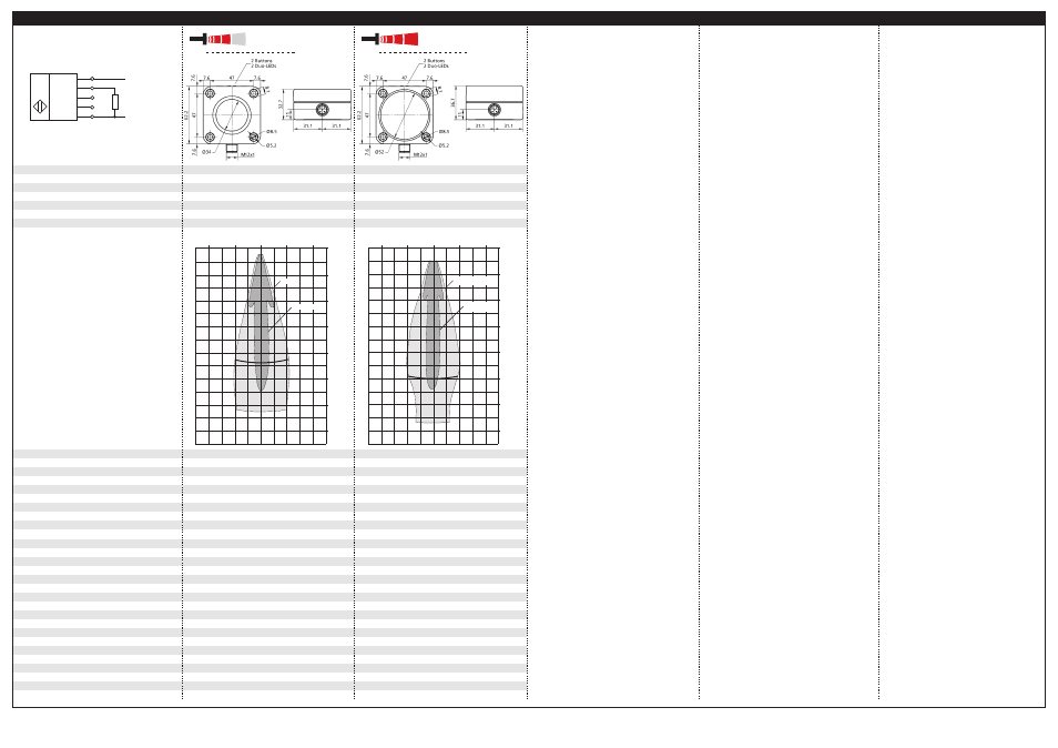
detection zones
for different objects:
The dark grey areas represent the zone
where it is easy to recognise the normal
reflector (round bar). This indicates the typical
operating range of the sensors. The light
grey areas represent the zone where a
very large reflector – for instance a
plate – can still be recognized. The
requirement here is for an optimum
alignment to the sensor. It is not
possible to evaluate ultrasonic
reflections outside this area.
120 kHz
0.18 mm to 1.5 mm, depending on the
80 kHz
0.18 mm to 2.4 mm, depending on the
analogue window
analogue window
reproducibility
accuracy
operating voltage U
B
± 0.15 %
±1 % (temperature drift internally compensated; may
± 0.15 %
±1 % (temperature drift internally compensated; may
be deactivated, 0,17 %/K without compensation)
9 V to 30 V DC, reverse polarity protection
be deactivated, 0,17 %/K without compensation)
9 V to 30 V DC, reverse polarity protection
voltage ripple
no-load current consumption
housing
±10 %
≤ 60 mA
±10 %
≤ 60 mA
PBT, Polyester; ultrasonic transducer:
polyurethane foam, epoxy resin with glass content
PBT, Polyester; ultrasonic transducer:
polyurethane foam, epoxy resin with glass content
class of protection per EN 60 529
type of connection
controls
programmable
IP 67
5-pin M12 circular plug, PBT
IP 67
5-pin M12 circular plug, PBT
2 push-buttons
• Teach-in via push-buttons
2 push-buttons
• Teach-in via push-buttons
indicator
synchronisation
operating temperature
• LCA-2 with LinkControl
LED D1 green/red (object within/outside margins)
• LCA-2 with LinkControl
LED D1 green/red (object within/outside margins)
internal synchronisation up to 10 sensors
-25°C to +70°C
internal synchronisation up to 10 sensors
-25°C to +70°C
storage temperature
weight
response time
1)
time delay before availability
1)
-40°C to +85°C
180 g
-40°C to +85°C
240 g
172 ms
< 450 ms
240 ms
< 450 ms
norm conformity
order no.
current output 4 - 20 mA
EN 60947-5-2
EN 60947-5-2
lcs+340/IU
R
L
≤ 100 Ω at 9 V ≤ U
B
≤ 15 V;
lcs+600/IU
R
L
≤ 100 Ω at 9 V ≤ U
B
≤ 15 V;
voltage output 0 - 10 V
R
L
≤ 500 Ω at U
B
≥ 15 V
rising/falling output characteristic
R
L
≤ 500 Ω at U
B
≥ 15 V
rising/falling output characteristic
R
L
≥ 100 kΩ at U
B
≥ 15 V, short-circuit-proof
rising/falling output characteristic
R
L
≥ 100 kΩ at U
B
≥ 15 V, short-circuit-proof
rising/falling output characteristic
1) Can be programmed with LinkControl
analogue output
+U
B
-U
B
IU
Sync/Com
1
2
4
5
3
U
lcs+340...
lcs+600...
0 m
0,8 m
1,6 m
2,4 m
3,2 m
4 m
4,8 m
5,6 m
3,4 m
plate
round bar
1,6 m
0,8 m
0 m
0,8 m
1,6 m
0 m
1,2 m
2,4 m
3,6 m
4,8 m
6 m
7,2 m
8,4 m
plate
round bar
2,4 m
1,2 m
0 m
1,2 m
2,4 m
*B10635*
MV-DO-121025-438274
microsonic GmbH | Hauert 16 | 44227 Dortmund | Germany | telefone +49 2 31 / 97 51 51-0 | telefax +49 2 31 / 97 51 51-51 | e-mail: [email protected] | www.microsonic.eu
The content of this document is subject to technical changes. Specifications in this document are presented in a descriptive way only. They do not confirm any product features.