Microsonic dbk+5/3CDD/M18 E+S User Manual
Page 2
2004/108/EC
Operation in the free-run
mode
The dbk+5 operates in the free-run
mode ex-works. In the free-run
mode, the dbk+5 performs measure-
ments cyclically.
Pointer
■ If measurements should be taken
in the shingled stream, then an ex-
ternal trigger signal can individu-
ally trigger each measurement. To
this end, the trigger mode can be
parameterized with the help of
the LCA-2 LinkControl adapter
available as an accessory and the
LinkControl software.
Fig. 3: Voltage level of the logic states at
the control inputs
Sensitivity classes
The fact that the dbk+5 control in-
puts are unconnected or on logic 0
points to pre-selection of the »Stan-
dard« sensitivity class where the
range of sheet material weights from
a typical 100 g/m
2
up to 2,000 g/m
2
can be scanned.
■ The 3 control inputs allow the sen-
sitivity classes to be pre-selected in
keeping with the Fig 4 table.
■ The »Thin« setting has to be se-
lected for thin materials.
■ The working range can be en-
larged to thicker materials by
choosing the setting »Thick«.
■ Changes
between
sensitivity
classes can be undertaken under
on-going operations.
■ Pre-selecting an over-low sensitiv-
ity class can result – even with a
single sheet – in a double sheet
signal appearing. In such an in-
stance, the next-higher sensitivity
class is to be pre-selected.
■ Pre-selecting an over-high sensitiv-
ity class results – given a single
sheet – in the double-sheet detec-
tion indicating overmodulation at
the LEDs: one LED lights up green
and the other green-red (orange
Logical state
0
Voltage level
pnp
-U
B
npn
+U
B
1
+U
B
-U
B
blend). In such an instance, the
next-lower sensitivity class is to be
pre-selected.
Pointer
Parameterization of the D1 switched
output onto the »Overmodulation«
output function achieved with Link-
Control software results in the over-
modulation signal being additionally
outputted on D1.
Teach-in
The teach-in mode is also available
for materials glued to each other
across their full extent (e.g. two wa-
fers bonded with a water film, a
spline on a paper web) and special
materials which cannot be scanned
with one of the 3 sensitivity classes
▸ Select the teach-in mode (C1 and
C2 on logic 1) in keeping with the
table in Fig 4.
This is the way to teach-in a material:
▸ Place a single sheet of the material
in the working range of the dou-
ble sheet detection.
▸ Place the C3 control input on logic
1 for a minimum of 3 seconds.
Materials with inhomogeneities
must be moved during the teach-
in phase so that dbk+5 can detect
them.
Success with a teach-in operation is
shown by a green LED. In instances
of where no material teach-in was
possible, dbk+5 flashes in red. Then
repeat the operation.
▸ On finishing the teach-in opera-
tion, either place the C3 control
input on logic 0 or leave it uncon-
nected.
The material can now be scanned.
Pointer
■ C3 must not be on logic 1 when
the supply voltage is connected.
Fig. 4: Free-run mode: selection of the sen-
sitivity class and Teach-in
Parameterization with Link-
Control
The dbk+5 can be extensively pa-
rameterized under LinkControl. Here
you need the optionally available
LinkControl adapter LCA-2 and the
LinkControl software for Windows©.
Operation onto LinkControl
▸ Install the LinkControl software
onto your PC.
Connect the LinkControl adapter
to your PC with the USB cable.
▸ Connect dbk+5 to the LCA-2 in
keeping with the Fig 5 table. For
this, use the adapter cable in the
LCA-2 case.
▸ Connect the voltage supply cable
to the LCA-2 on the other side of
the T connector.
▸ Start the LinkControl software and
follow the instructions on the
screen.
Fig. 5: Connecting dbk+5 to the LCA-2
The following settings can be under-
taken:
■ Numeric input of the spacing be-
tween transmitter and receiver
■ Function for the D1 switched out-
put
Missing sheet = NCC (single sheet
= NCO) or
Missing sheet = NCO (single sheet
= NCC) or
Overmodulation = NCC or
Overmodulation = NOC
Standard
Thick
C1
C2
0
0
0
1
C3
0
0
Thin
Teach-in-Mode
Teach-in active
1
1
0
1
1
1
0
0
1
+U
B
-U
B
Colour
dbk+5
Colour
adapter cable
Brown
Blue
Brown
Blue
Pin
1
3
C3/Com
Grey
Grey
5
■ Function for the D2 switched out-
put
Double sheet = NCI or
Double sheet = NCO
■ Operating mode
Free-run mode with 3 pre-defined
sensitivity classes and additional
teach-in mode or
Free-run mode with 4 indepen-
dent teach-in classes or
Trigger mode with 2 pre-defined
sensitivity classes and additional
teach-in mode or
Edge- or level-controlled trigger
mode
Also available is a diagrammatic re-
presentation of the readings.
Operation in the trigger
mode
If LinkControl was used to parame-
ters the trigger mode, then the exter-
nal trigger signal is to be placed on
the C2 control input.
Available in the trigger mode are
sensitivity classes »Standard«, »Thin«
and the teach-in mode in keeping
with the Fig 6 table.
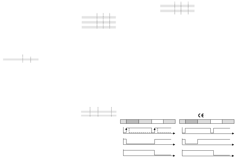
In the edge-controlled trigger setting
(see Fig 7), the double sheet detec-
tion takes a measurement with every
edge from 0 to 1. The finding is then
stored until the next trigger edge.
Fig. 6: Trigger mode: selection of the sensi-
tivity class and teach-in mode
In the level-controlled trigger mode,
dbk+5 keeps on taking measure-
ments for as long as the trigger sig-
nal is on hand. With dbk+5 deacti-
vated (C2 control input to logic 0),
the reading of the last measurement
at the switched outputs is frozen (see
Fig 8).
Free-run mode with 4 inde-
pendent teach-in classes
Parameterization with the aid of
LinkControl of the free-run mode
with 4 independent teach-in classes
makes teach-in possible for up to 4
different materials. As a result, the
»Standard«, »Thick«, »Thin« and
»Teach-in mode« sensitivity classes
can be individually adjusted (see on-
line help in LinkControl).
Teach-in spacing between
transmitter and receiver
Teach-in of the selected spacing be-
tween transmitter and receiver must
be undertaken should you not have
mounted transmitter and receiver at
the recommended 40 mm or 30 mm
spacing.
▸ Clear the measuring section of
sheet materials between transmit-
Standard
Thick
C1
C2
0
0
Trigger
Trigger
C3
0
1
Teach-in-Mode
Teach-in active
1
1
Trigger
Trigger
0
1
ter and receiver.
Place all the 3 control inputs on
logic 1.
Switch on the supply voltage: The
LEDs flash alternately red and
green.
Wait at least 2 seconds.
Place the C3 control input on logic
0.
Pointer
■ Any failure to teach-in the set
spacing results in dbk+5 flashing
in red for 3 seconds.
dbk+5 is operating normally. Finally,
select the requested type of opera-
tion through the control inputs.
Maintenance
No maintenance is need on the dou-
ble sheet detection. We would re-
commend cleaning the sensor sur-
faces at the transmitter and receiver
should they become very dirty. The
best thing is to apply some isopropa-
nol onto a cotton cloth and then
wipe the surface clean. Make sure
that the reaction time of the cleaner
is kept down. That means quickly
wiping dry the transducer surfaces.
Double sheet
Missing sheet
Single sheet
Assingnment
1
0
t
1
0
t
1
0
t
Control input C2
Double sheet output
Missing sheet output
Double sheet
Missing sheet
Single sheet
Assingnment
1
0
t
1
0
t
1
0
t
Control input C2
Double sheet output
Missing sheet output
Fig.7: Trigger mode edge-controlled
Fig. 8: Trigger-mode level-controlled