2 rear view, 1 fc-3g-eo-18, 2 fc-3g-eo-36 – Nevion Flashlink Compact II User Manual
Page 13
Flashlink Compact II
Rev. A
nevion.com | 13
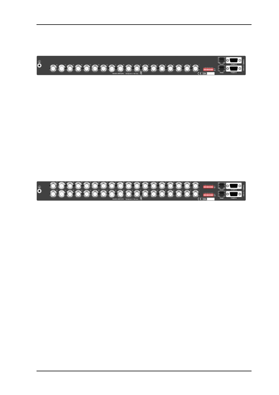
2.2 Rear view
2.2.1 FC-3G-EO-18
Earth point:
For connection to internal earth bar in 19”
BNC:
Electrical 3G/HD/SD-SDI inputs.
DIP 1 to 8:
Configures the Flashlink Compact II. See chapter 5 for more information.
Upper RS422: RJ45 connector for connection for Multicon Gyda.
Lower RS422: RJ45 connector for daisy chaining more Flashlink Compact II. This must be
terminated when not used.
Power A:
Main DC input connector. Standard 9pin DSUB. Pin 4 is positive voltage
and pin 1 is ground.
Power B:
Spare/redundancy DC input connector. Standard 9pin DSUB. Pin 4 is
positive voltage and pin 1 is ground.
2.2.2 FC-3G-EO-36
Earth point:
For connection to internal earth bar in 19”
Upper BNC:
Electrical 3G/HD/SD-SDI inputs.
Lower BNC:
Electrical 3G/HD/SD-SDI inputs.
DIP 1 to 8:
Configures the Flashlink Compact II. See chapter 5 for more information.
(upper and lower)
Upper RS422: RJ45 connector for connection for Multicon Gyda.
Lower RS422: RJ45 connector for daisy chaining more Flashlink Compact II. This must be
terminated when not used.
Power A:
Main DC input connector. Standard 9pin DSUB. Pin 4 is positive voltage
and pin 1 is ground.
Power B:
Spare/redundancy DC input connector. Standard 9pin DSUB. Pin 4 is
positive voltage and pin 1 is ground.