3 connections, 1 pin-out power a and power b (db9), 1 pin-out rs-422 (rj45) – Nevion Flashlink Compact II User Manual
Page 16: 3connections
Flashlink Compact II
Rev. A
nevion.com | 16
3
Connections
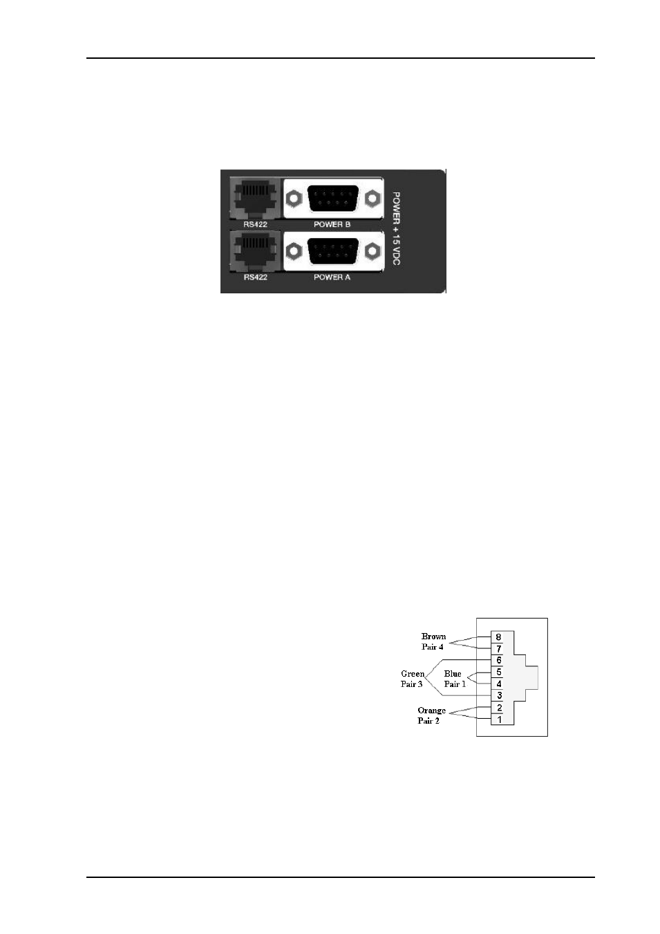
1.1 Power connection
Figure 3 shows the power connections of the unit as well as the RS-422 connections.
Figure 1 - Connector module for the power supply.
The Power inputs are constructed to provide redundancy when using two external power
supplies. When supplying power to one of the connectors it is not possible to source power
from the second power connector. Tighten the screws to ensure a proper contact.
The power inputs are DB9 male connectors.
1.1.1 Pin-out POWER A and POWER B (DB9)
Pin #1
GND
Pin #4
+15V
1.2 RS-422 connection
At the rear of unit it is two RJ45 connectors. These are used for Flashlink RS422 control
bus.
The RS-422 interfaces are shown in figure 3.
1.2.1 Pin-out RS-422 (RJ45)
Pin #1
Rx A (+)
Pin #2
Rx B (-)
Pin #3
Tx A (+)
Pin #4
Reserved
Pin #5
Reserved
Pin #6
Tx B (-)
Pin #7
Not Connected
Pin #8
Not Connected