Nevion HD-TD-10GX-8-SFP User Manual
Page 14
HD-TD-10GX-8
Rev. A
nevion.com | 14
be ignored in manual mode. The module will still answer status requests from Multicon, and
Multicon can thus still be used to monitor the module and trigger alarms in the event of errors.
Note that the switch that selects operating mode is only read at start-up, i.e. to go from DIP
switch control to Multicon control (or vice versa) the switch position must be changed and the
module restarted. The inward postion (i.e. to right in the illustration below) is manual mode
and the outward position is Multicon controlled mode.
Illustration 6: Location of the manual/Multicon control switch
The top DIP switch on the board is used to disable the laser when this is switched to the
inward position. It is important for the module to be set to 'manual' mode in order for any of
the other DIP switches to work. The four DIP switches bellow this one are used to set the
direction of the four bidirectional ports. The default setting is for these is to be set to outputs,
and so switching these to the inward position will set the channels to be inputs.
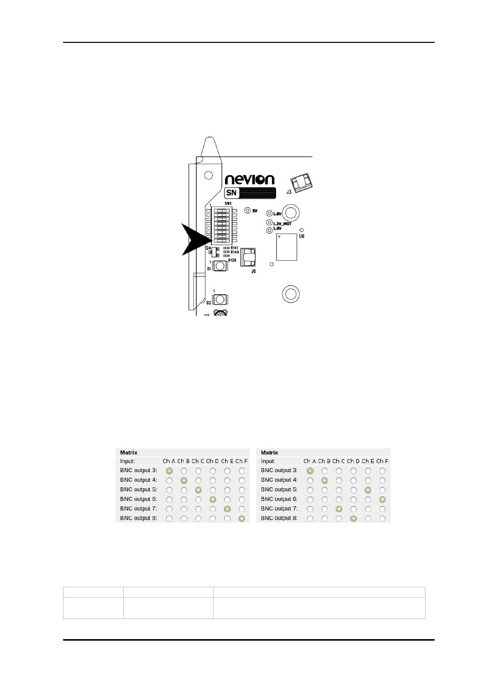
The switch below this is be used to change the output matrix from the default setting to an
alternative setting of the four bidirectional channels' output, in order to test the signals using
a confidence loop. These two settings are shown in the illustration below.
The table below shows the DIP switches and their functions. The numbering starts from the
top of the card. The inward position on the card refers to the DIP switch being
set to ‘on’.
Switch #
Function name
Function DIPs
1
Laser
On: Laser is disabled
Off: Laser is enabled
Illustration 7: Diagonal matrix (left) and alternative matrix (right)