Module status, Gyda system controller (optional), Led’s at the front of the sub-rack – Nevion ADC-SDI-CC User Manual
Page 11: 1 gpi alarm – module status outputs, Electrical maximums for gpi outputs, Max current: 100ma, Max voltage: 30v, Adc-sdi-cc module gpi pinning, Signal, Name
ADC-SDI-CC
Rev. 3
DATE: 23 July 2008
Network Electronics AS, P.O.Box 1020, N-3204 Sandefjord, Norway. Tel.: +47 33 48 99 99 – Fax: +47 33 48 99 98
E-mail: [email protected] – Web: http://www.network-electronics.com/
Technical specifications are subject to be changed without notice.
11
5. Module status
The status of the module can be monitored in two ways.
1. GYDA System Controller (optional).
2. LED’s at the front of the sub-rack.
The LED’s are mounted on the module itself, whereas the GYDA System Controller is a separate module
which gives detailed information on the card status. The functions of the LED’s are described on the next
page. The GYDA controller is described in a separate user manual. This manual is available on our web
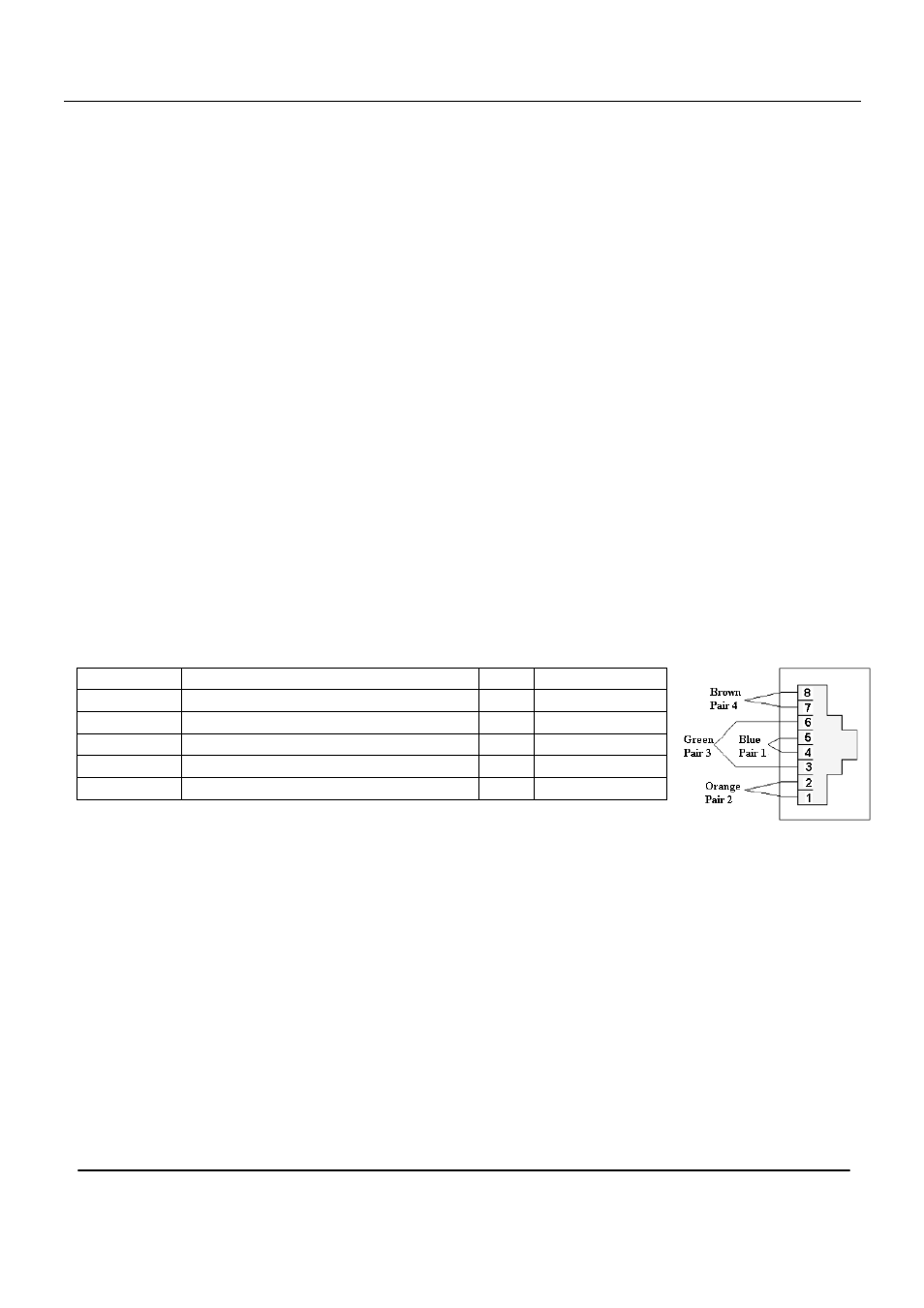
5.1 GPI ALARM – Module Status Outputs
These outputs can be used for wiring up alarms for third party control systems. The GPI outputs are open
collector outputs, sinking to ground when an alarm is triggered. The GPI connector is shown in Figure 4 .
Electrical Maximums for GPI outputs
Max current: 100mA
Max voltage: 30V
ADC-SDI-CC module GPI pinning:
Signal Name
Pin
#
Mode
Status
General error status for the module.
Pin 1 Open Collector
Input
No video input detected
Pin 2 Open Collector
VCXO
Module not gen-locked to video input Pin 3 Open Collector
SDI Output No SDI output present
Pin 4 Open Collector
Ground
0 volt pin
Pin 8 0V.
Figure 4 - GPI Outlet