Connector module, Figure 2 - adc-sdi-cc-c1 connector module, 1 correspondence of connectors and signals – Nevion ADC-SDI-CC User Manual
Page 7: The adc-sdi-cc-c1 connector module has 7 bnc's, Cvbs/y, Analogue input: cvbs, sync for rgb or s-video luma, R/pr, Analogue input: red or component pr, Analogue input: green or component y, B/pb/c
ADC-SDI-CC
Rev. 3
DATE: 23 July 2008
Network Electronics AS, P.O.Box 1020, N-3204 Sandefjord, Norway. Tel.: +47 33 48 99 99 – Fax: +47 33 48 99 98
E-mail: [email protected] – Web: http://www.network-electronics.com/
Technical specifications are subject to be changed without notice.
7
3. Connector module
The
ADC-SDI-CC
has a dedicated connector module:
ADC-SDI-CC
-C1. This module is mounted at the
rear of the sub-rack. The module is shown in Figure 2 .
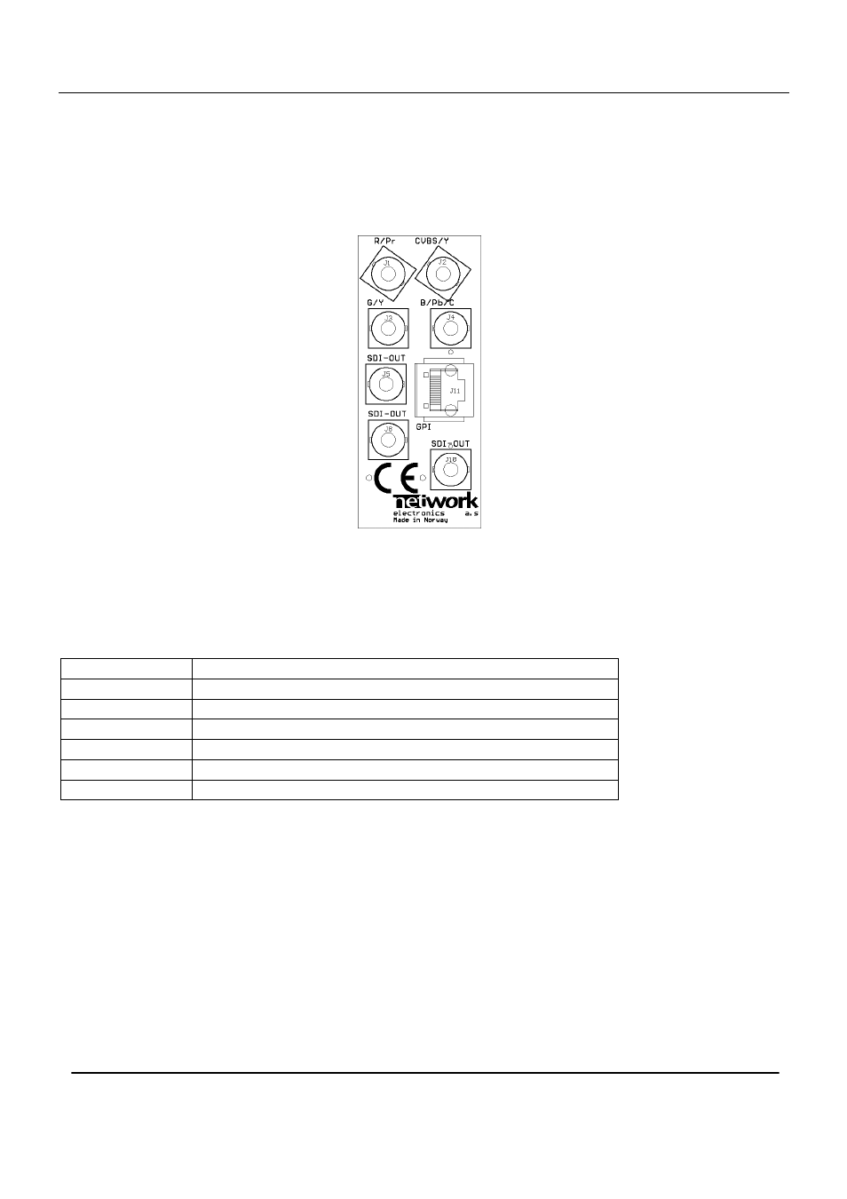
Figure 2 - ADC-SDI-CC-C1 connector module.
3.1 Correspondence of connectors and signals
The ADC-SDI-CC-C1 connector module has 7 BNC's:
CVBS/Y
Analogue input: CVBS, SYNC for RGB or S-Video Luma.
R/Pr
Analogue input: Red or component Pr.
G/Y
Analogue input: Green or component Y.
B/Pb/C
Analogue input: Blue, component Pb or S-Video Chroma.
SDI-OUT
Digital SDI output
SDI-OUT
Digital SDI output
SDI-OUT
Digital SDI output
SDI1, SDI2 and SDI3 are equivalent SDI outputs.
Note: The analogue inputs are internally terminated with 75
Ω on the ADC-SDI-CC card.
3.2 Mounting the connector module
The details of how the connector module is mounted, is found in the user manual for the sub-rack frame
FR-2RU-10-2.
This manual is also available from