NIStune Z32 ECU User Manual
Page 5
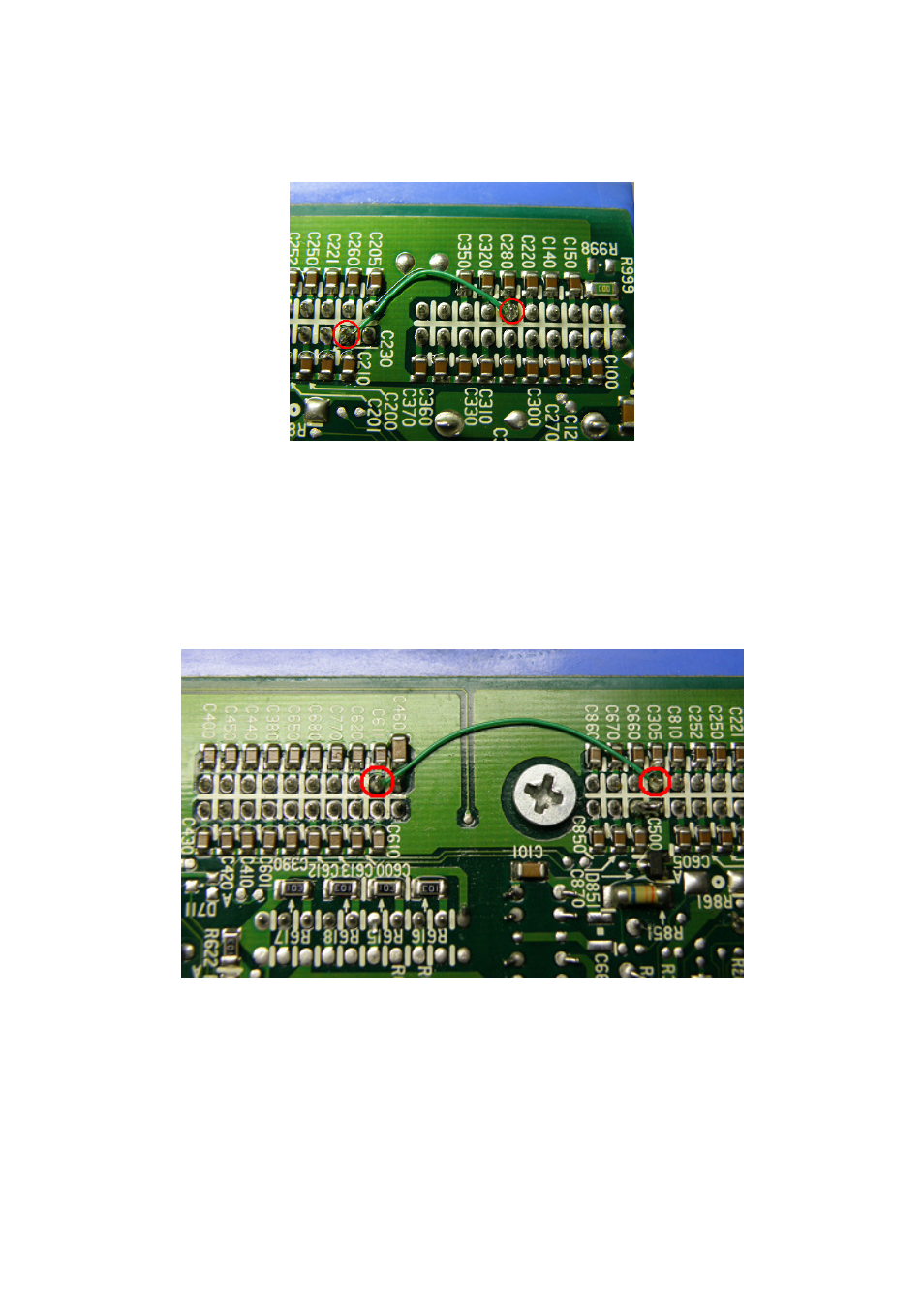
2) O2 Sensor inputs – pin 29/55
RB25 uses a single O2 sensor. Z32 uses twin. Link the O2 sensor input for RB25 (pin 29)
to pin 55 so both O2 sensor inputs (LHS and RHS) receive a signal. This avoids the
potential condition of RHS bank being open circuit (and assigned a default value of 0.3
volts by the ECU) meaning a potentially lean condition.
Link pins 29 - 55
3) Power Steer switch input – pin 19/34
RB25 power steering input goes to pin 19. This pin is used to drive the rad fan relay on
Z32, so this signal must be moved to the Z32 power steer input pin (pin 34). This is
achieved by linking across two pins and then isolating the original drive signal by removing
a resistor on the top side of the board.
Link pins 19 – 34
The resistor is R613. To find it, check that the blue harness connector is facing you. Then
identify where the plastic spacer comes through the circuit board. R613 is located 1.5cm to
the left and slightly down. This isolates the output driver for the rad fan relay.