Troubleshooting – Orion System MHGRV II User Manual
Page 10
Technical Guide
MHGRVII Controller
10
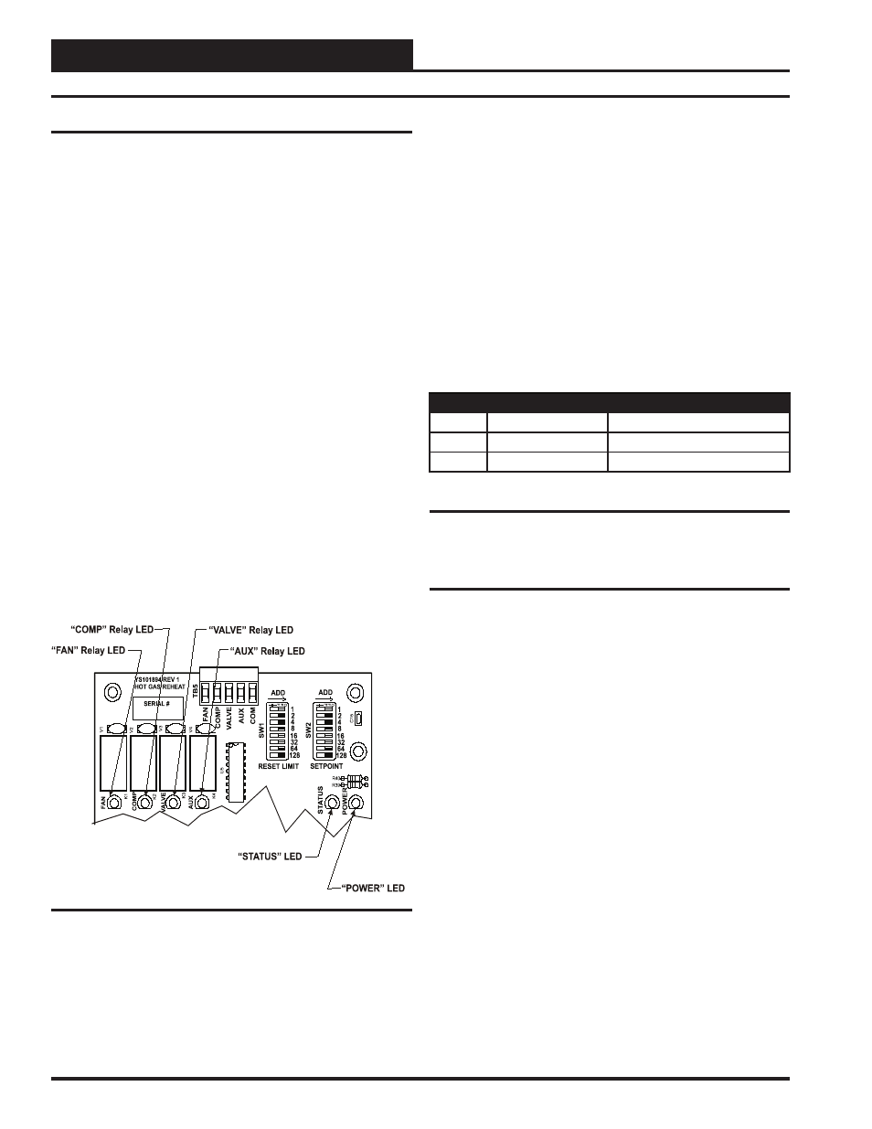
Using LED’s To Verify Operation
The MHGRV II controller is equipped with LEDs that can be used as
very powerful troubleshooting tools. The MHGRV II controller board
has six LEDs. Two of these LEDs are used in troubleshooting. See Fig-
ure 12 for the LED locations. The LEDs and their uses are as follows:
LED Descriptions
“STATUS”
This is the diagnostic blink code LED. It will light up and blink out
diagnostic codes.
“PWR”
This LED will light up to indicate that 24 VAC power has been applied
to the controller.
“FAN”
This light indicates that the relay for the “FAN” output is energized and
it’s Normally Open Contact is closed
“COMP”
This light indicates that the relay for the “COMP” output is energized
and it’s Normally Open Contact is closed.
“VALVE”
This light indicates that the relay for the “VALVE” output is energized
and it’s Normally Open Contact is closed
“AUX”
This light indicates that the relay for the “AUX” output is energized and
it’s Normally Open Contact is closed
Figure 6: LED Locations
LED Diagnostics
“PWR” LED
When the MHGRV II Controller is powered up the “PWR” LED should
light up and stay on continuously. If it does not light up, check to be sure
that the power wiring is connected to the board, that the connections are
tight and the transformer is powered. If after making all these checks
the “PWR” LED does not light up, the board is probably defective.
“STATUS” LED
As previously described when the board is fi rst powered up the LED
will do the following:
One Blink
Off for fi ve seconds
Blinks 30 times
Blinks 3 times rapidly
Status code is repeatedly blinked every ten seconds to
indicate controller status
Table 1: STATUS LED Blink Codes
Only the highest priority failure code will be shown. You must correct
the highest priority alarm before other problems will be indicated.
Other Checks
Supply Air Temperature Sensor
If you suspect the Supply Air Temperature Sensor is not reading cor-
rectly, make sure the wiring terminal connections are tight and that any
wiring splices are properly connected. You can check the operation
of the Supply Air Temperature Sensor by measuring the resistance or
voltage using a digital multimeter. Set the meter to DC Volts. Place
the positive probe on the AIN terminal and the negative probe on the
GND terminal. Read the DC Volts and fi nd that voltage in Table 2 on
the following page. Read the temperature corresponding with that volt-
age and determine if this is close to the actual temperature the sensor is
exposed to. If the temperature from the chart is different by more than
a few degrees you probably have a defective or damaged sensor. You
can also check the sensor resistance to determine correct operation. To
read the resistance set the meter to Ohms. Unplug the sensor connector
from the board and measure the resistance across the disconnected wires.
This resistance should match the corresponding temperature from Table
2 on the following page.
Troubleshooting
Priority Number Of Blinks
Status
Lowest
1
Normal Operation
-
2
SAT Over High Limit
Highest
3
Bad SAT Sensor