Dip switch settings, Supply air temperature reset limit – Orion System MHGRV II User Manual
Page 7
MHGRVII Controller
Technical Guide
7
Supply Air Temperature
The DIP switches are only used when the controller is installed as a
stand-alone controller. The main unit controller will set the Supply Air
Temperature Setpoint and Reset Limit when the MHGRV II is used as
an expansion device.
The user can set the desired Discharge Air Temperature Setpoint using
the DIP Switch labeled SETPOINT. See Figure 4 for location and DIP
Switch setting instructions. The MHGRV II controller will allow the user
to set a Supply Air Temperature Setpoint between 50°F and 100°F. If a
value of less than 50°F is set, the controller will default to a 50°F Supply
Air Temperature Setpoint, a value greater than 100°F will cause the unit
to default to a 100°F Supply Air Temperature Setpoint.
Supply Air Temperature Reset Limit
The user can reset the Supply Air Temperature Setpoint by supplying
a 0-10 VDC control signal to the Reset Input (RST IN) terminal on the
MHGRV II controller board. The reset range is determined by the RESET
LIMIT DIP Switch. See Figure 4 for location and setting instructions.
The controller will reset the Supply Air Temperature Setpoint from the
value set on the SETPOINT DIP Switch to the value set on the RESET
LIMIT DIP Switch, as the Reset Input (RST IN)
signal is increased from 0 Volts to 10 Volts..
Example:
We want the Discharge Air Temperature Setpoint to increase from 55°F
when the Reset Input signal is at 0 Volts, to 75°F when the Reset Input
signal is at 10 Volts.
Set the SETPOINT DIP Switch to 55°F
Set the RESET LIMIT DIP Switch to 75°F
The discharge air temperature will now increase from 55°F to 75°F as
the Reset Input voltage signal ramps from 0 Volts to 10 Volts.
Note: It is possible to create a “reverse acting” control sequence.
Using the temperatures from the example above by set-
ting the SETPOINT DIP Switch to 75
F and the RESET
LIMIT DIP Switch to 55
F, the reset would be reverse
acting. In this case the controller will maintain a 75
F
discharge temperature when the Reset Input signal is at
0 Volts and will reduce it to 55
F when the Reset Input
signal is at 10 Volts.
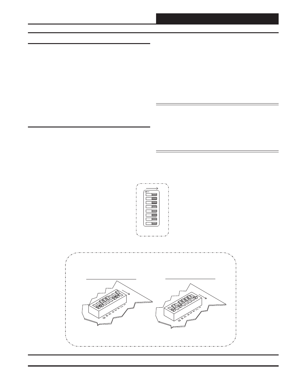
DIP Switch Settings
DIP Switch Setting Shown
Is For A Setpoint Of 57
DIP Switch Setting Shown
Is For A Setpoint Of 94
ADD
ADD
32 + 16 + 8 + 1 = 57
64 + 16 + 8 + 4 + 2 = 94
All Rocker Switches Depressed
In the Direction Of The ADD Arrow
Are Added Together To Total The Setpoint
Typical DIP Switch
Detail View
F
1
O
F
ADD
4
2
16
8
64
32
128
Figure 4: DIP Switch Setting Instructions