Mhgrvii controller technical guide 5 – Orion System MHGRV II User Manual
Page 5
MHGRVII Controller
Technical Guide
5
V1
K1
V2
K2
V3
K3
K4
V4
YS101894 REV 1
HOT GAS REHEAT
SERIAL #
R2
R17
R23
FA
N
COMP
VA
LV
E
AUX
U5
CX5
STEP
C2
C4
R9
R8
R7
R13
R5
R6
D4
D3
R4
D2
PU
R12
D6
R11
R1
D5
R3
R3
R20
R19
R18
L1
D1
16
16
F
RESET LIMIT
O
F
4
4
2
2
1
1
8
8
64
64
32
32
128
128
ADD
SETPOINT
ADD
F
O
F
R40
R39
ST
A
TUS
POWER
VA
LV
E
AUX
FA
N
COMP
COM
TB5
SW1
SW2
U1
0-10V
4-20MA
THERM
AUX
IN
SETUP
C15
PJ1
+VDC
GND
GND
AUX IN
RST IN
HTG OVR
CLG OVR
GND
SAT
RHT EN
T
SHLD
R
CR/HG
CW/HW
CB/HB
CG/HR
TB3
COMM
VR1
RV
1
C13
R31
D1
D11
C3
U2
V5
C8
L2
C12
C1
+24VAC
GND
TB4
R38
R2
D1
WDOG
CX6
U6
U1
CX1
C3
R1
U2
1
EPROM
CX2
RAM
U5
C2
P1
C4
YS101818
552
PROCESSOR
BOARD
C1
X1
CX5
U3
U4
CX4
CX3
I
C
OUT
2
IC
IN
2
Fan
Setpoint
DIP Switch
Must Be Set
For Required
Supply Air
Temperature
Reset Limit
DIP Switch
Must Be Set
For Required
Reset Supply
Air Temperature
“VALVE” Relay LED
“AUX” Relay LED
“COMP” Relay LED
“FAN” Relay LED
“POWER” LED
“STATUS” LED
RAM Chip
EPROM Chip
Black
Black
White
White
Red
Red
Green
Green
Compressor
HGR Solenoid Valve
2 Position HGR Valve (Optional)
24 VAC
Line
GND
24V
AC
Supply
Air Temperature
Sensor
40 VA
Transformer
Minimum
-
+
0-10VDC
External Reset
Signal
Heating Override
H1 (Dehumidification)
Cooling Override
Condensor
Modulating
HG Valve
Reheat
Modulating
HG Valve
C1
C2
Mount In Supply
Air Duct
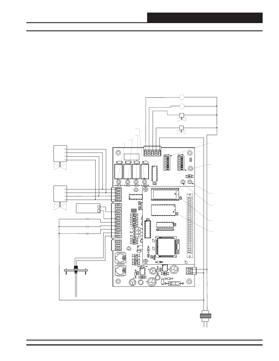
Figure 2: MHGRV II Controller Wiring When Used As A Stand-Alone Controller
Please carefully read and apply the following information when wiring
the MHGRV II controller.
1. All 24 VAC wiring must be connected so that all ground
wires remain common. Failure to follow this procedure
can result in damage to the controller and connected
devices.
2. All wiring is to be in accordance with local and national
electrical codes and specifi cations.
3. Minimum wire size for 24 VAC wiring should be 18
gauge.
4. Minimum wire size for all sensors should be 24 gauge.
5. Be sure that all wiring connections are properly inserted
and tightened into the terminal blocks. Do not allow wire
strands to stick out and touch adjoining terminals which
could potentially cause a short circuit.