Controller overview, Vav/zone controller 3 technical guide general, Features – Orion System MHGRV II User Manual
Page 3: Operation, Figure 1: mhgrv ii controller dimensions, The mhgrv ii provides the following features, Reheat enable command
VAV/Zone Controller
3
Technical Guide
General
The MHGRV II Controller is designed to control a Modulating Hot
Gas Reheat Valve to maintain a desired Supply Air Temperature and
Humidifi cation setpoint . The controller can be used as a stand-alone
controller or it can be connected to and used in conjunction with the
AAON Factory Packaged HVAC unit controller. The MHGRV II control-
ler is connected to the HVAC unit controller via a modular expansion
cable and corresponding connectors on the controllers.
Features
The MHGRV II provides the following features.
Can Be Operated as a Stand-Alone Controller or Integrated
with the HVAC Unit Controller
Provides for Supply Air Temperature Setpoint
Reset when Required
Second Stage Reheat Capability When Using
2 Hot Gas Reheat Valves
Control of Reheat Solenoid Valve to
Provide Coil Flushing for Positive Refrigerant Oil
Return
Operation
When used in a stand-alone application (not connected to an HVAC unit
controller board) the MHGRV II controller will control the Modulating
Hot Gas Valve to maintain the Supply Air Setpoint based on the Supply
Air Temperature Sensor connected to the MHGRV II controller. The
MHGRV II controller is activated by a 24 VAC wet contact closure
Controller Overview
signal connected to the H1 (RHT EN) input terminal on the controller.
Heating Override and Cooling Override are also controlled by 24 VAC
wet contact closure signals connected to the HTG OVR and CLG OVR
input terminals on the controller. The Supply Air Setpoint is set by
confi guring a DIP switch on the MHGRV II controller board. Supply
Air Temperature Reset is also available and is set by confi guring a DIP
switch on the controller board. When Supply Air Temperature Reset is
used it is reset by a 0-10 VDC signal supplied to the RST IN terminal
on the MHGRV II controller.
When the MHGRV II controller is connected to an HVAC unit control-
ler board via its modular cable it will operate exactly as the stand-alone
controller except the following information will be passed between the
MHGRV II controller and the HVAC unit controller.
Reheat Enable command
Supply Air Temperature Setpoint. This replaces the
setpoint that is set with the Supply Air Temperature DIP
switch on the MHGRV II controller.
The Reset Supply Air Temperature Setpoint. This replaces
the setpoint that is set with the Supply Air Temperature
Reset DIP switch on the MHGRV II controller. The Supply
Air Temperature Reset Signal is also supplied from the
HVAC unit controller.
If the communication is interrupted between the MHGRV
II controller and the HVAC unit controller, the
MHGRV II controller will revert to stand-alone operation.
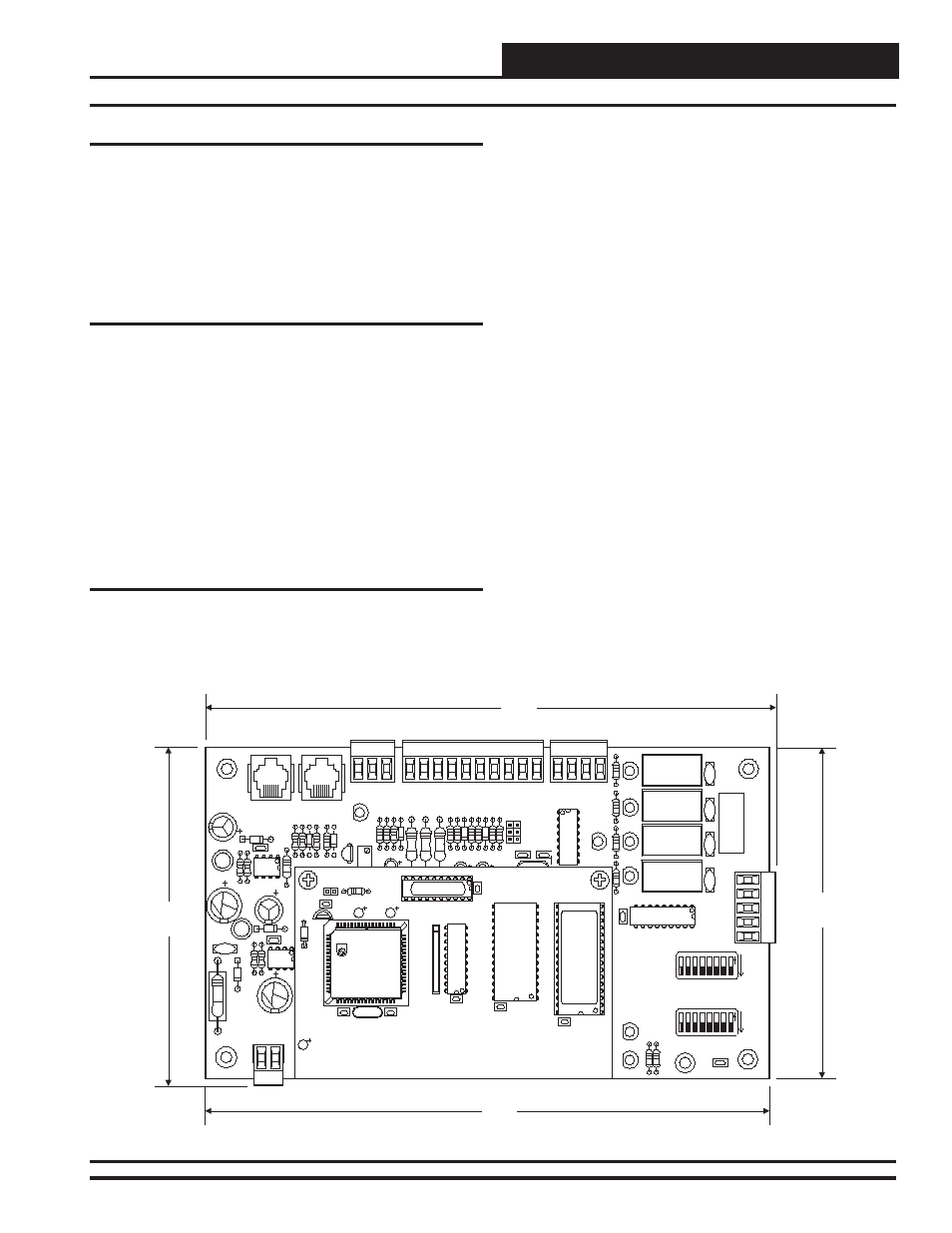
Figure 1: MHGRV II Controller Dimensions
V1
K1
V2
K2
V3
K3
K4
V4
YS101894
REV
1
HOT
GAS
REHEA
T
SERIAL
#
R2
R17
R23
FAN
COMP
VALVE
AUX
U5
CX5
STEP
C2
C4
R9
R8
R7 R13
R5 R6
D4
D3
R4 D2
PU
R12
D6
R1
1
R1
D5
R3
R3
R20
R19
R18
L1
D1
16
RESET
LIMIT
4 2 1
8
64 32
128
ADD
4
SETPOINT
32
128 64
16 8
ADD
1
2
R40
R39
STATUS
POWER
VALVE
AUX
FAN
COMP
COM
TB5
SW1
SW2
U1
0-10V
4-20MA
THERM
AUX IN
SETUP
C15
I C OUT
2
PJ1
2
I C IN
+VDC
GND
GND
AUX
IN
RST
IN
HTG
OVR
CLG
OVR
GND
SA
T
RHT
IN
T
SHLD
R
TB3
COMM
VR1
RV1
C13
R31
D1
D1
1
C3
U2
V5
C8
L2
C12
C1
+24V
AC
GND
TB4
R38
R2
D1
WDOG
CX6
U6
U1
CX1
C3
R1
U2
1
EPROM
CX2
RAM
U5
C2
P1
C4
YS101818P552
PROCESSOR
BOARD
C1
X1
CX5
U3
U4
CX4
CX3
4.80"
4.69"
8.10"
8.01"
CR/HG
CW/HW
CB/HB
CG/HR